adjacent floodplain elevation. We also tested 8-ft-tall
addition, any ice releases should be gradual, not cata-
5-ft-wide, 45 sloped blocks to compare their perfor-
strophic, and the ICS should have minimal environmen-
tal impact and low operation and maintenance require-
mance with the cylindrical piers and to compare their
ments. The objectives of the model tests were to quan-
model behavior with the field behavior of the Hard-
tify the ice-retention capability of the new ICS, opti-
wick ICS.
mize pier spacing, and determine design ice loads.
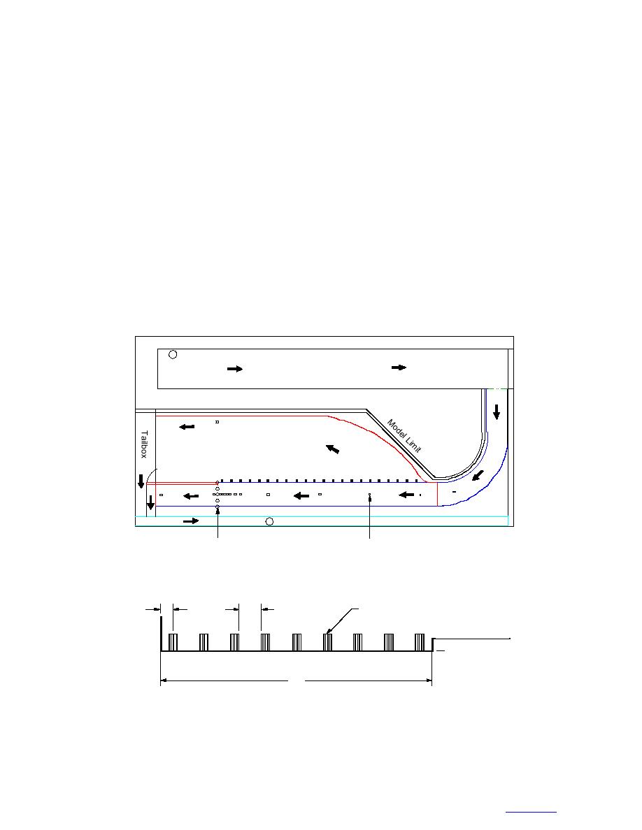
Figure 6 shows a plan view of the 1:15-scale refrig-
We designed the physical model based on our expe-
erated hydraulic model of Cazenovia Creek used to
rience with the sloped-block ICS (Lever et al. 1997).
develop the cylindrical-pier ICS. The model covered
In particular, we selected a large scale-factor (1:15 un-
about 2000 ft of river length and 560 ft of width, and
distorted) to study the unsteady ice-jam processes that
included most of the adjoining floodplain. The ICS was
occur near the ICS. For vertical piers, the gap between
located in a channel section about 150 ft wide (Fig. 7).
piers, rather than their diameter or shape, should have
Time series measurements in the model included inflow,
the strongest effect on the ICS's ice-retention capabili-
floodplain, and channel discharges, channel and flood-
ty. Therefore, we tested only 5-ft-diameter cylindrical
plain water-surface elevations, and loads on five piers.
piers and varied gap width from 1014 ft. Tests of the
Sample rate was 2.6 Hz (prototype scale). Single-axis
sloped-block ICS indicated that they could retain ice
load cells measured downstream overturning moments
jams that rose about 3 ft above the tops of the blocks.
on four of the ICS piers (M1M4), while a six-axis load
We therefore selected a single pier height, 10 ft above
cell measured downstream and transverse overturning
the average bed elevation at the ICS cross-section,
moments and downstream force on one pier (Fig. 7).
which placed the top of the piers about 3 ft above the
We calibrated the load cells before each test and zeroed
Pump Discharge
Ice Supply Flume
Weir
EL
.6
45
Natural
Floodplain
Flow Cut
Off Wall
Trees
River Channel
Gate
Weir
Drain
Ice Control Structure
Water Level Transducers
(810 Piers, 5 ft dia.)
(16 Locations)
Figure 6. Plan view of 1:15-scale refrigerated hydraulic model of Cazenovia Creek. Chan-
nel width at the ICS is 150 ft, and the overall length modeled is about 2000 ft.
7
12
5 dia., EL 644
EL 641 Floodplain
EL 634
M4
M3
6-axis
M2
M1
150
Figure 7. Elevation view of ICS consisting of nine 5-ft-diameter 10-ft-tall
cylindrical piers with 12-ft gaps. Dimensions and elevations (EL) are prototype
feet. Piers M1M4 were equipped with single-axis load cells to measure downstream
overturning moments, and a six-axis load cell to measured downstream and trans-
verse moments and downstream force.
5
TO CONTENTS


 Previous Page
