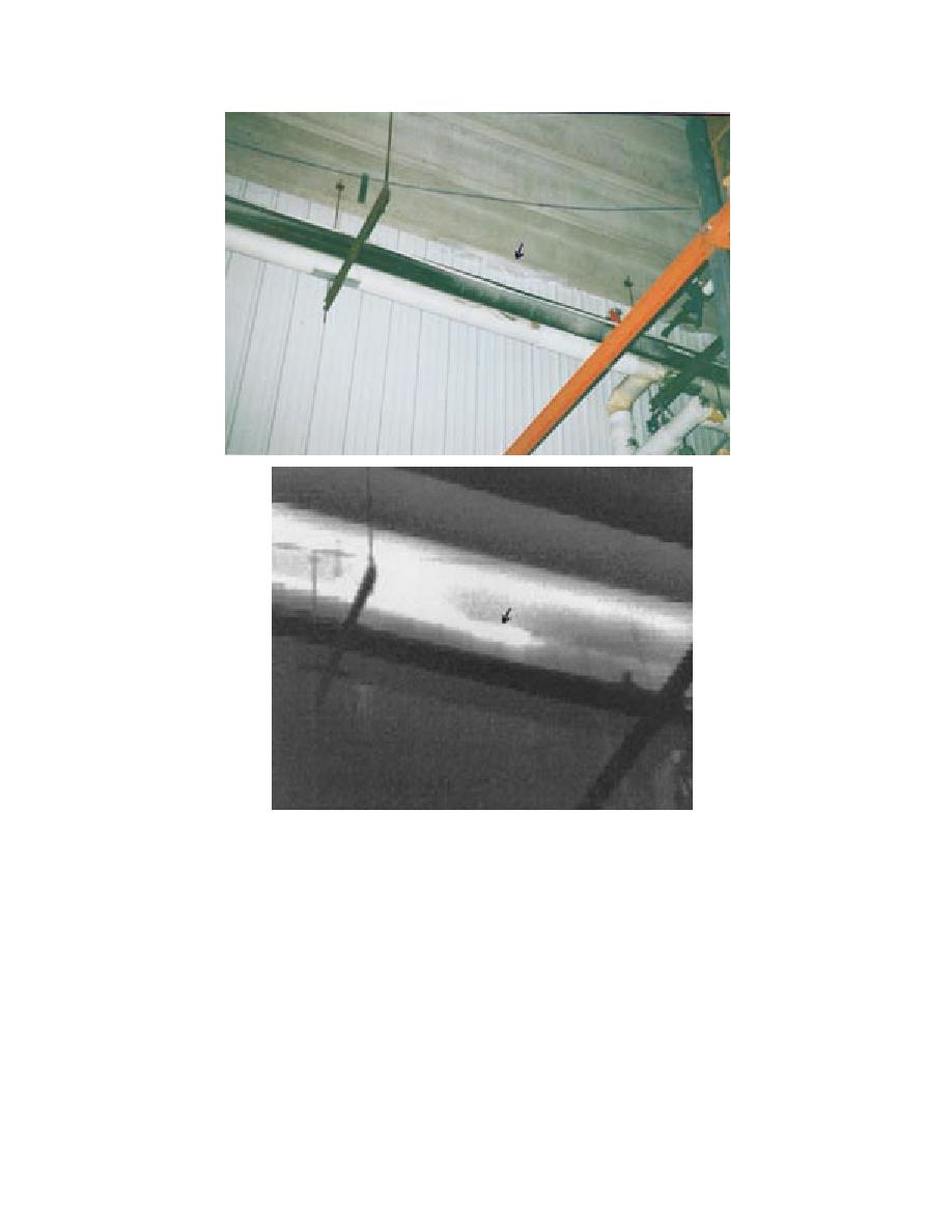
Figure 10. Photograph and thermogram from within the D1 freezer,
showing ice and air infiltration where the roof and wall join.
thane foam may be worth considering. Warming
a photograph and a thermogram of the area along
this freezer could also be used to melt the ice in
the north side of the building where the roof and
the fibrous glass insulation. The meltwater would
wall join. Ice is visible in the photograph and the
probably leak out of the roof between the concrete
bright thermal image indicates that warm outdoor
double-tees, thereby drying out the wet fibrous
air is leaking into the freezer along this seam. Fig-
glass insulation and recovering much of its lost
ure 11 shows similar images taken of the north-
east corner. Frost has accumulated there as warm
insulating ability.
outdoor air infiltrates into the freezer. Figures 10
Most of the waterproofing membrane on this
and 11 indicate that air infiltration is occurring
roof is in good condition. It may be wise to revise
along the roof-wall intersection. The next time this
the north edge of this roof to eliminate the prob-
freezer is warmed up, it may be appropriate to take
lem shown in Figure 5. It may also be appropriate
steps to seal this joint. Spraying it with polyure-
to replace the stone ballast with roof pavers in the
7


 Previous Page
