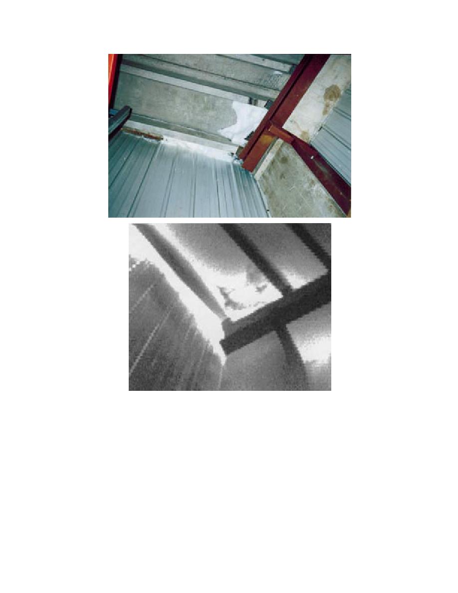
Figure 11. Photograph and thermogram from within the D1 freezer
showing frost, ice, and air infiltration in the northeast corner of the
D1 freezer where the two walls and roof join.
perature of the freezer below this roof was 0F.
northeast and northwest corners, and perhaps all
along the north edge, to prevent ballast scour there.
The daytime visual inspection revealed no roof-
Pavers are more stable in high winds.
ing defects. During the nighttime on-the-roof in-
frared survey, large bright thermal anomalies were
detected in the southeast corner. A few marks were
made with orange spray paint there to define the
ROOF D2
general extent of these bright areas. Figure 12
This roof consists of a ballasted EPDM mem-
shows a photograph and a thermogram of this cor-
brane, expanded polystyrene insulation (2 in.), an
ner of the roof. Figure 13 shows a photograph and
old bituminous built-up membrane, fibrous glass
a thermogram of a small rhombic anomaly also in
insulation (7 in.), and a concrete deck. The tem-
this general area. That wet area is also visible at
8


 Previous Page
