where τ1 is the fast relaxation time from eq 36 and the
jth type of charge carriers are majority charge carriers.
Laboratory experiments
Today, we have an ample collection of experimen-
tal data on the generation of EME and electrical sig-
nals by cracks in ice. To the best of our knowledge, the
first laboratory0 measurements of electrical signals
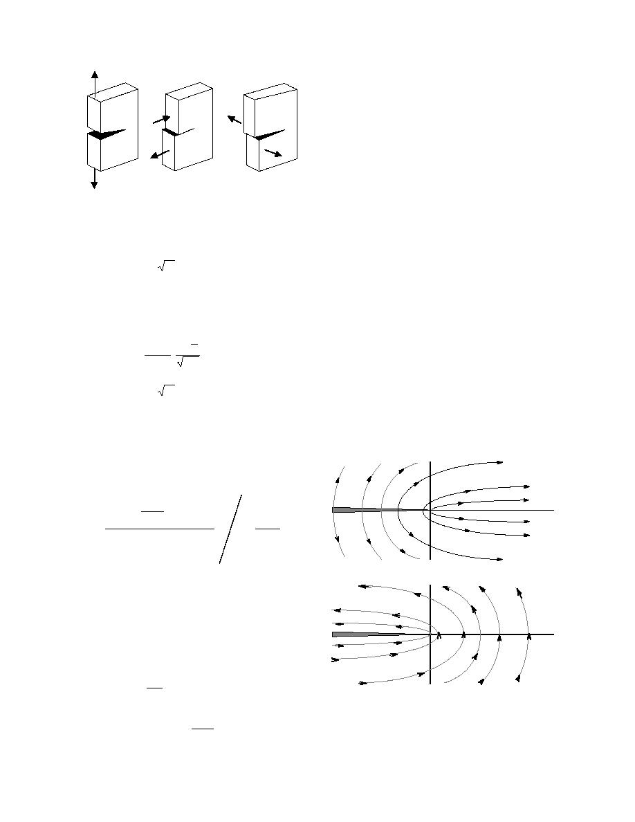
MODE I
MODE II
MODE III
from cracks were performed by Takahashi (1969b). He
measured an electrical charge generated by the break-
Figure 18. Three modes of cracks.
ing of frost under a temperature gradient. The frost was
grown either between two ice hemispheres or between
where ν is Poisson's ratio, E is Young's modulus and KI
two metal plates. Significant charge separation was
is an intensity factor
observed only under a temperature gradient, which
generates an electrical field E⊥ in the direction perpen-
KI = βσ(∞) πl
(48)
dicular to the cracks in the frost. The strength of elec-
trical field E⊥ of about 20 V/m at 15C was generated
where σ(∞) is tensile stress at infinity and l is the crack
by the thermoelectric effect in ice. The density of the
length. The numerical coefficient β depends on bound-
electrical charge separated by cracks in frost was esti-
mated by Takahashi as 106 C/m. That value exceeds
ary conditions and is about 1. For the mode II crack
by about one order of magnitude the charge density
θ
predicted by eq 33. The discrepancy may be explained
(1 - ν)
sin
2
εii = KII
⋅
(49)
by the break in the frost occurring at the narrowest
2πr
E
neck, where the temperature gradient, and hence E⊥ ∝
∇T, exceed their average magnitudes.
KII = βτ(∞) πl
(50)
Takahashi (1983) expanded his study of charge sep-
aration by cracks in single-crystalline ice samples.
where again β is about 1 and τ(∞) is shear stress at infin-
During those experiments, both sample cross section
ity (Hellan 1984).
and the temperature gradient were well defined. Again,
For stable cracks or cracks that move "slowly," i.e.,
cracks for which the time of their motion is longer than
the electrical relaxation times, the system of eq 4346
has a solution (Petrenko 1993a)
α jσ j
+ ej Dj∇nj
-∇ε ii ⋅
Φεεo
r
ej
1 + 2 .
E=
σj
ej
(51)
MODE I
Figure 19 shows force lines of an electrical field gen-
erated by mode I and mode II cracks in ice. Estimates
made using eq 4751 show that a typical electrical
potential difference between infinity and a crack in-
creases from 10100 mV at the crack's tail to about 1 V
at the crack's tip.
The electrical field generated by a rapidly growing
crack can be calculated as
exp(-t / τ1)
1
E = (t, r ) = -
r
r
εε0
(52)
MODE II
Figure 19. Lines of force of the electric field in-
α jσ j
t
∫ [exp(ξ / τ1)]
∇εij (ξ, r )dξ
duced by stable mode I and mode II cracks in ice
r
ej
(after Petrenko 1993a).
0
16


 Previous Page
