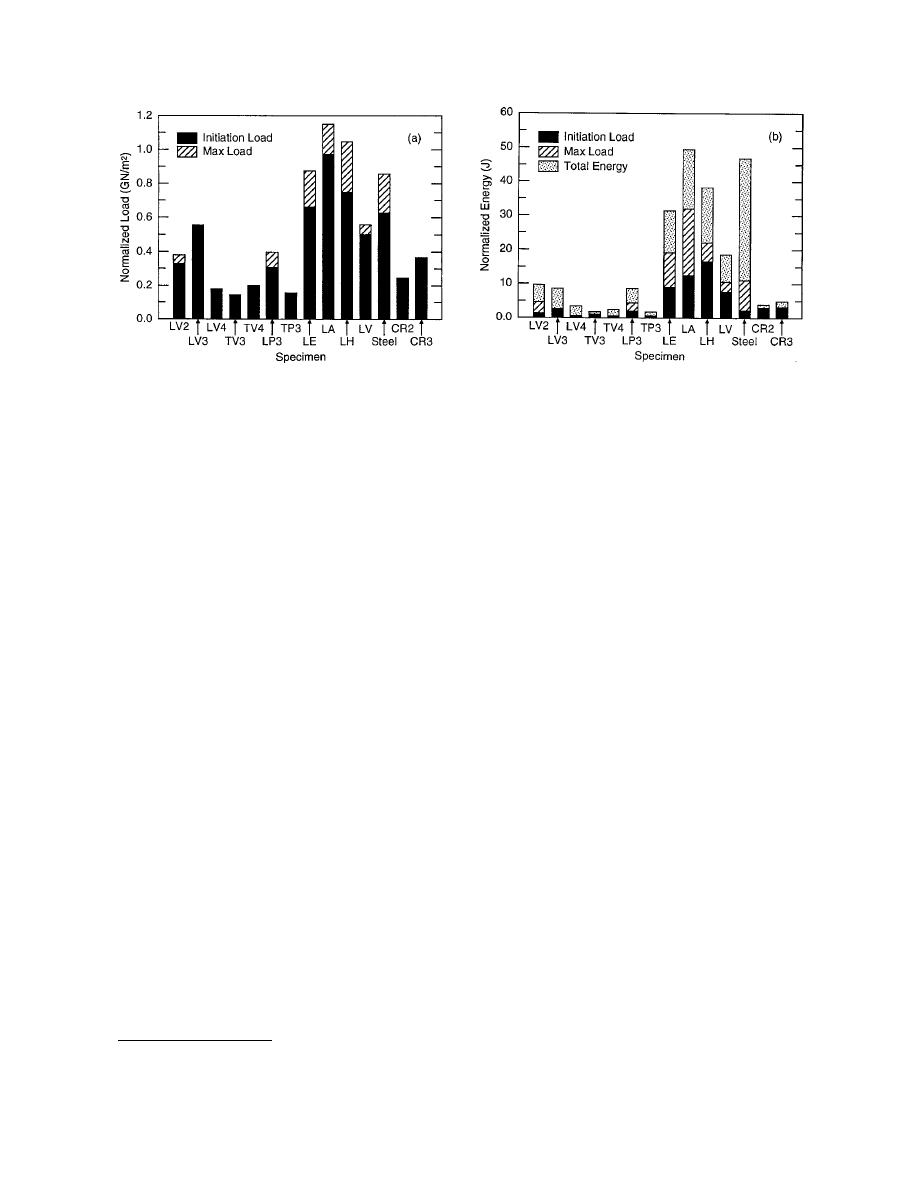
a. Comparison of normalized loads for the W-beam
b. Comparison of normalized energy for the W-beam
composites with other composites.
composites with other composites.
Figure 36. Comparison of normalized loads and energy for the W-beam composites with other composites.
at the post-yielding or fracture phase. This phe-
h = half thickness
nomenon is expected, because steel is much more
I = moment of inertia of the cross-
ductile than FRP, as was evident from the initial
sectional area.
test results given in Figures 8a and b for the quasi-
The geometric portion of this relationship
static test condition. It is also interesting to note,
(Lh/4I) was used to normalize the load when
from the results in Figure 36b, that suitable fiber
specimens of different sizes were used in the test,
architecture in pultruded composites can maxi-
including those obtained from the FRP W-beam.
mize the energy absorption. Unfortunately,
The average loadtime history of the five CR2
under this series of tests no results were avail-
specimens is shown in Figure 35a; the results for
able for the 12.7-mm (0.5-in.) thick W-beam FRP
CR3 specimens are shown in Figure 35b. The cor-
materials, which are more relevant for the one-
responding energies are shown in Figures 35c and
to-one replacement of the steel W-beam.
d, respectively. The results produced by Svenson*
for comparison with other pultruded composites
Discussion
tested earlier by Svenson et al. (1993) are shown
The FRP beams for the above exploratory tests
in Figure 36a for a normalized load, and Figure
were fabricated in W-beam profiles using the
36b for normalized energy. Figure 36b clearly
design approaches of composite structures avail-
reveals that the FRP W-beam rail composites fab-
able to commercial vendors of small batch pro-
ricated for the current investigation absorbed very
ductions. The bidirectional reinforcements of
little energy compared to many other commer-
stitched E-glass and S-2 glass mats in 21 layers
cially available pultruded composites, especially
(12.7-mm- [0.5-in.-] thick profile) were placed in
when they contain a large amount of longitudi-
a matrix of isophthalic polyester in a sequence
nally oriented fibers. It is interesting to note, how-
such that in both the longitudinal and transverse
ever, that both CR2 and CR3, which are only 6.35
directions, the strengths were above 413.4 MPa
mm (0.25 in.) and 9.53 mm (0.375 in.) thick, respec-
(60,000 psi), which is slightly more than the
tively, absorb higher amounts of energy (see cross
strength of the conventional steel W-beam. Under
hatching in Fig. 36b) before the initiation of yield-
the applied load, the material failed in tension
ing or fracture than does the steel, indicating that
through interlaminar shear failure and fiber frac-
not much energy is absorbed by the composites
ture before complete separation (Fig. 17). Thus,
the stress-strain characteristic (Fig. 18b) shows
quite a brittle behavior. This spectacular brittle
behavior is primarily because no shear-load-
* A.L. Svenson, L.W. Hargrave, and L.C. Bank, personal com-
bearing 45 oriented fibers were present. Replace
munication, 1996.
24


 Previous Page
