Table 5. Comparison of steel and FRP W-beams of different thicknesses.
Nominal
Nominal
Moment
Flexural
Flexural
Nominal
Nominal
Weight
tensile
Young's
of inertia
stiffness
yield
size
section
per ft
strength
modulus
(I)
(EI)
load
(psi 103)
(psi 106)
4 104)
2 1010)
(in.2)
Material
(in.)
(lbf)
(in.
(lbf in.
(lbf)
FRP
0.5
9.58
6.09
60.0
2.0
11.8
23.6
20.0
FRP
0.375
7.56
4.81
60.0
2.0
8.8
17.6
12.0
FRP
0.25
5.25
3.34
60.0
2.0
5.6
11.2
6.0
Steel
0.111
2.12
7.12
60.0
30.0
2.3
69.3
14.0
SI conversion factors: 1 in. = 25.4 mm, 1 in.2 = 645.2 mm2, 1 lbf = 4.45 N, 1 psi = 6.89 kPa.
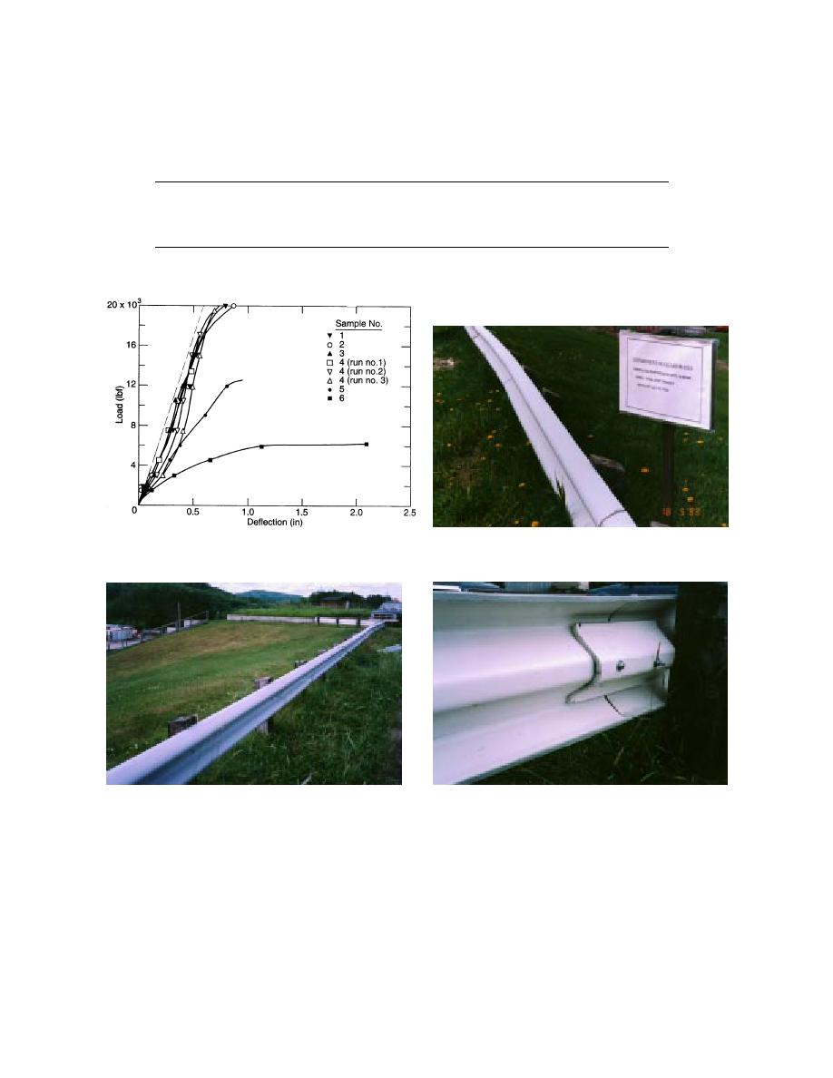
Runs 14 = 0.5
Run 5 = 0.375
Run 6 = 0.25 in
Figure 29. Results from the load-deflection tests of the
Figure 31. End-on-end epoxy glued joint.
FRP W-beams.
Figure 30. CRREL's pilot installation of the 12.7-mm-
Figure 32. Splicing by cut-out piece of W-beam.
(0. 5-in.-) thick FRP W-beam.
within the CRREL campus, a site was available
July 1992, a length of approximately 35 m (120
for a pilot installation of this rail using nonstand-
ft) of these rails was installed, end-on-end was
ard wooden posts (Fig. 30). This would provide
epoxy glued (Fig. 31), and back spliced with a
an opportunity for observing any degradation of
shorter piece of W-beam cut-out which was fas-
this material due to the cold and long-term
tened with nuts and bolts (Fig. 32). Until the
weather exposure of New Hampshire, under a
demolition of the installation in the spring of 1996,
controlled and noncritical traffic environment. In
no major blistering or any other signs of material
22


 Previous Page
