degradation was noticed. However, in the win-
Impact test
ters, the installation suffered severe snow accu-
An impact test of the 6.35-mm (0.25-in.) and
mulation and was subjected to snow plowing (Fig.
9.53-mm (0.375-in.) W-beam materials, designated
33); as a result, immediately after the first winter,
as CR2 and CR3, respectively, was conducted by
the surface veil coating was observed to be
Svenson (1993) at the Turner-Fairbank Highway
removed at several places (Fig. 34).
Research Center of the FHWA in conjunction with
their intensive studies of "Impact Behavior of
Composites." The results of the impact testing of
a number of commercially available pultruded
composites conducted using an MTS (Model
850.02A-01) vertical drop weight testing machine
were reported at the 1993 Annual Conference of
the Composites Institute, and readers are encour-
aged to read the article to review the detailed pro-
cedures of the test. The tests were conducted by
dropping a striking cylinder head perpendicular
to the specimen's broad surface at the center of a
simply supported span. Load (P), energy (E), and
velocity (v) were measured from the acceleration
history of the impact. For the striker weight w,
and acceleration a, these parameters were given
Figure 33. The FRP W-beam installation exposed to
by
heavy snow accumulation and plowing.
P = ma
(5)
v = g ∫ a dt
(6)
and
E = ∫ Pv dt.
(7)
To compare test results, such as load and energy,
from different specimens, the authors used a nor-
malizing procedure using the maximum elastic
bending stress equation:
σ = (2PLh)/(4I)
(8)
where σ = maximum bending stress
P = load
Figure 34. Snow plow abrasion damage to the FRP
L = length of the specimen
beam.
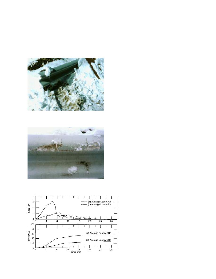
Figure 35. Average load-time history of (a)
6.35-mm- (0.25-in.-) thick CR2 and (b) 9.53-
mm- (0.375-in.-) thick CR3 specimens under
impact test. Average energy absorbed in (c)
6.35-mm- (0.25-in.-) thick CR2 and (d) 9.53-
mm- (0.375-in.-) thick CR3 specimens under
impact test.
23


 Previous Page
