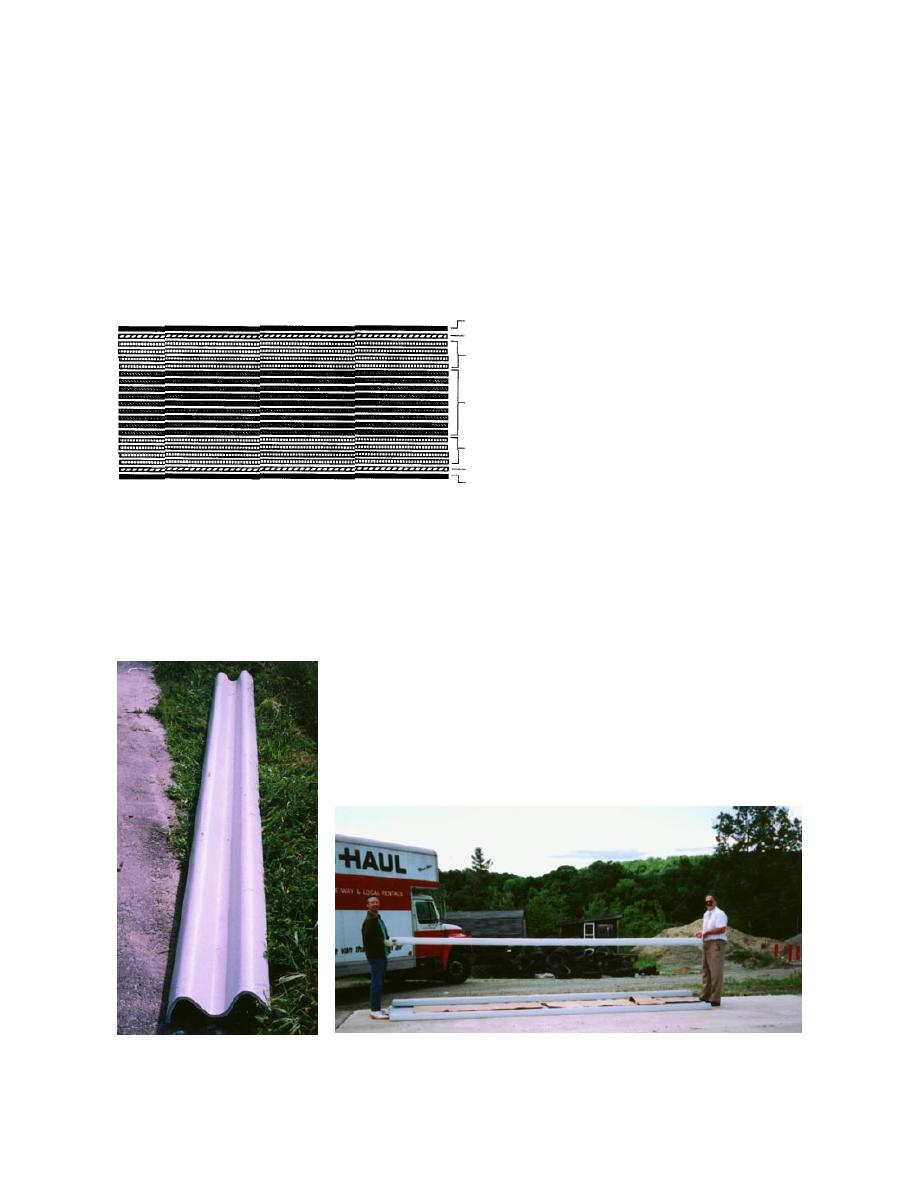
required, their profile almost mimicked the con-
Spliced bolt tension tests
ventional guardrail (Fig. 20). The flexural stiffness
Since W-beam rails have to be spliced together
(and also connected to end shoes), tension tests
of the beams also proved to be adequate as can
were conducted to evaluate the strength and per-
be seen in Figure 21 in which hardly any sagging
formance of the bolted splice joints. There was
was noticed when a beam was held at the two
ends. Some lengths of 6.35-mm (0.25-in.) and 9.53-
concern that the reinforced plastic might fail in
bearing at the bolts.
mm- (0.375-in.-) thick W-beams were also manu-
The configuration of the 19.05-mm (0.75-in.)
factured, with a reduced number of internal
layers.
bolt pull-out test is shown in Figure 22a. For these
tests from the flat portions of the 12.7-mm- (0.5-
in.-) thick W-beams eight rectangular test cou-
Glass Fiber Reinforcements in
pons (Fig. 23) of 304.8 63.5 mm (12 in. 2.5
Half Inch W-Beam Construction
C1
E1 in.) size were cut and machined. At 38.1 mm
S4 (1.5 in.) from the edge at each end, 19.05-mm-
(0.75-in.-) diam. holes were drilled to accom-
modate the 19.05-mm (0.75-in.) bolts of
E9 tensioning D-links connected to 25.4-mm- (1.0-
in.-) diam. eye-bolts. The loads were applied
in tension to the eye-bolts by a servohy-
S4
draulically operated testing machine with a
E1
cross-head speed of 2.54 mm (0.1 in.) per
C1
minute (Fig. 22b). The test results are summa-
C1 One layer of a C-glass mat
E1 One layer of bidirectional stitched E-glass
rized in Table 4.
S4 Four layers of S-2 (unidirectional) 0 and 90 alternate
The load-displacement curves from the
E9 Nine layers of bidirectional stitched E-glass
above tests, superimposed on each other, are
Resin: MR 12311 Isophthalic Polyester
shown in Figure 24. A failed specimen show-
Catalyst: MEKP
Gel Coat: AG-3752M #96 Silver Metallic
ing the failure cracks, one longitudinal and one
Density: 1.46 gm/cm3 (0.053 lb/in.3)
transverse, is shown in Figure 25.
Figure 19. Layup of the final FRP W-beam construction.
Considering the nominal area of the W-beam
for the 12.7 63.5 mm (0.5 2.5 in.) section as
806.5 mm2 (1.25 sq. in.), the nominal stress on the
beam at which the bolt failure occurred is approxi-
mately 57.435 MPa (8,336 psi). This is only about
14% of the desired maximum tensile strength of
the FRP W-beam. This is a distinct disadvantage,
and future work would be needed to adequately
reinforce the bolt holes in the FRP W-beams.
Figure 20. FRP W-beam as pro-
Figure 21. Prototype 6.1-m (20-ft) long W-beam held at two ends that did not
duced from the design.
sag under its own weight.
18


 Previous Page
