cedures described in ASTM D5084. The large-
were separated using a sheet of PVC geomem-
brane that did not extend to the outer edge of the
diameter flexible-wall permeameter was used to
GCL (Fig. 3). The PVC captured water seeping
test specimens having a diameter of 12 in. (30 cm).
through the GCL, but allowed water leaking
Procedures in ASTM D5094 were used for tests in
through the edge seal to bypass the collection sys-
the larger-scale flexible-wall cell. Detailed descrip-
tem and flow out through a different drain. The
tions of the equipment and test methods are pro-
pea gravel beneath the PVC geomembrane was
vided by Chamberlain et al. (1990).
sloped to a drain pipe where the water was col-
We did 12 laboratory freezethaw tests in the
lected.
CRREL rigid-wall freezethaw permeameter
Hydraulic conductivity was measured through
(three each on the three soils, and one each on the
December 1993 until the water in the test pans
GCLs). Specimens were prepared in the laboratory
began to freeze. Measurements were restarted in
from samples taken from the site during construc-
April 1994. On 3 June 1994, several of the test pans
tion. The clays were compacted in the laboratory
emitted a strong septic odor, indicating some
to match field conditions, and placed in the CRREL
amount of biological growth. About 1 L of chlor-
freezethaw permeameter for testing. The confin-
ing pressure was maintained at 1 lb/in.2 (6.9 kPa),
ine bleach was added to each test pan in an
attempt to reduce the biological growth and pre-
and the hydraulic gradient was maintained
vent clogging of the system. After the chlorine was
between 2 and 5 during freezethaw testing. The
added, it appeared that the closed collection sys-
GCLs were tested in a similar manner.
tem may have been limiting the amount of water
Each specimen was subjected to 15 freezethaw
that could seep through the GCLs. After identify-
cycles, with hydraulic conductivity being mea-
ing the potential problem, a change was made that
sured after the first, third, fifth, tenth, and fifteenth
allowed seepage to be collected in a way that
cycle. Following these freezethaw cycles, the
ensured free drainage.
Parkview and Valley Trail clays were tested after
confining pressures were increased incrementally
Electronic instrumentation
to see how this affected hydraulic conductivity.
Forty temperature sensors and an automated
weather station were installed to permit moni-
Laboratory tests on field specimens
toring of freezethaw cycles, frost depths, and
of compacted clay
related climatic conditions. The data were col-
Hydraulic conductivity tests were also per-
lected every 5 minutes using a datalogger. Average
formed on large- and small-diameter unfrozen
hourly values were saved and transferred to a com-
soil specimens. Specimens were removed from the
puter at the CRREL laboratory in New Hampshire
field test pads before, during, and after the winter
via computer modem and cellular phone link.
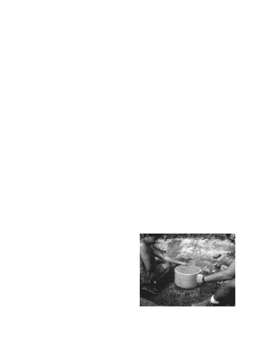
seasons of 199293 and 199394. Large-diameter
specimens (Fig. 4) of thawed clay and sand
bentonite were removed from the test pads by
Laboratory hydraulic conductivity
hand carving 12-in.- (30-cm-) diameter soil blocks
testing program
Hydraulic conductivity tests were performed
in the laboratory for comparison to measurements
made using the field permeameters. Three types
of permeameters were used in the laboratory test-
ing: 1) the rigid-wall CRREL freezethaw perme-
ameter (CRREL), 2) the conventional flexible-wall
permeameter (CRREL and UW-Madison), and 3) a
large-diameter flexible-wall permeameter (UW-
Madison).
The CRREL rigid-wall freezethaw permeame-
ter allows specimens to be frozen and thawed and
tested for hydraulic conductivity. The freeze
thaw cycle can be repeated many times, freezing
rates are controlled, and the freeze front moves
vertically. The conventional flexible-wall per-
meameter tests were conducted on unfrozen spec-
Figure 4. Taking a 12-in.- (30-cm-) diameter hydraulic
imens (diameter of 2.75 in. [7 cm]) following pro-
conductivity test specimen from the field.
7


 Previous Page
