Test site description
moisture-density meter. Relative compaction
exceeding 95% of the maximum dry unit weight
Clay and sand bentonite test pads
(measured by ASTM D698 procedures) was
Figure 1 shows the layout of the test site. Two
attained on each test pad. The water content was
test pads having thicknesses of 2 ft (0.6 m) (PV-2
2 to 5% of optimum wetness.
and VT-5), and two test pads of 3-ft (1-m) thick-
Thicknesses of the test pads and the cover ma-
ness (PV-3 and VT-4) were constructed for each of
terials were varied to model different conditions
the natural clays. One test pad having a 2-ft thick-
and to permit partial or full penetration of frost.
ness was constructed using the sandbentonite
The 2-ft- (0.6-m-) thick test pads (SB-1, PV-2, and
(SB-1).
VT-5) were covered with a layer of 0.5-mil.- (0.13-
The clay and sandbentonite test pads were 30
70 ft (9 21 m) to allow the compaction equip-
mm-) thick polyethylene and 4 in. (10 cm) of sand
to minimize desiccation. The 3-ft- (1-m-) thick
ment to achieve normal operating speed. This
Parkview test pad (PV-3) was covered with
size was also selected because it reduced the
needle-punched nonwoven geotextile and a 141-
chance that specimens to be collected would be
in.- (3.5-m-) thick gravel layer to model a typical
affected by edge effects. Construction was com-
clay linerleachate collection system used in Wis-
pleted in October 1992. The test pads were moni-
consin. The 3-ft- (1-m-) thick Valley Trail test pad
tored until being removed in July 1994.
was covered with a 1-ft- (0.3-m-) thick layer of
A layer of HDPE geomembrane was placed
well-graded sand without a geosynthetic layer.
over the subgrade (2% slope) and then covered
with a geocomposite drain (nonwoven geotextile
Field test-pad permeameters
on each side of a geonet). The geomembrane and
Rigid-wall, in-situ field permeameters were
geocomposite drain were used in the test pad per-
designed and installed in test pads SB-1, PV-2,
meameters. The HDPE also prevented water from
and PV-3 immediately after the pads were con-
migrating up into the test pads, and the drain
structed in 1992. The permeameters were de-
allowed construction water and seepage to drain
signed to allow testing of hydraulic conductivity
away from the bottom of the clay layer.
in the full liner section after freezethaw. A key
The natural clays were placed in 6-in.- (15-cm-)
design element was that the testing should not
thick loose lifts spread with a Caterpillar D3 bull-
disturb the soil structure created by the freezing
dozer and compacted with a Caterpillar 825
and thawing process.
tamping foot compactor. The compactor pad feet
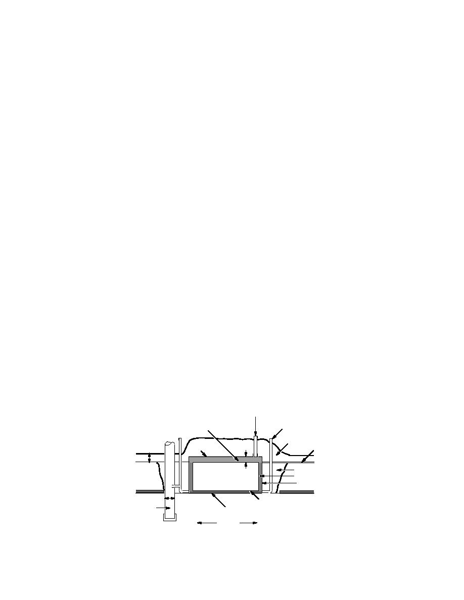
Figure 2 shows a section of the field per-
were 6 in. long, which allowed them to fully pene-
meameters. Construction consisted of carving
trate the loose lift onto the previously compacted
soil away to leave an undisturbed 4- 4-ft (1.3-
lift. This resulted in uniform compaction of the
1.3-m) block of clay or sandbentonite. An HDPE
loose lift. The sandbentonite was compacted
box, open at top and bottom, was placed around
with a vibrating compactor having a steel smooth
the block of clay, then seamed at the bottom to the
wheel. Unit weight was measured with a nuclear
2.5 cm Diameter
Riser Pipe
4 cm Minus
Vent Pipe
Drainage Gravel
Sand Cover
80 mil
6 mil PE
12 cm
HDPE Top
Vapor Barrier
10 cm
Compacted Clay Backfill
Clay or
Bentonite Grout
Test Pad
Sand-Bentonite
Block
0.6 cm HDPE Plate
20 cm
Fabrinet
Outflow
40 mil HDPE Liner
Collection Sump
Subgrade
Figure 2. Details of the field permeameters in the test pads.
5


 Previous Page
