b
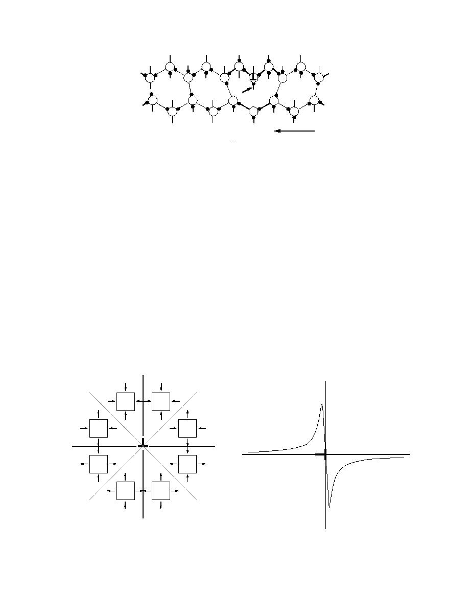
Figure 32. Section in the (1100) plane of a 60 dislocation
on a plane of the shuffle set in the structure of ice, illustrat-
ing the dangling bond in the core.
materials and semiconductors. Though there are no
such dangling bonds may exchange protons with an
theoretical papers on the electrical charge of disloca-
ice bulk.
tions in ice, some reasons for formation of such a
Second, a mechanism that may result in a net dislo-
cation charge is strong elastic interaction between a
charge are obvious.
protonic charge carrier--i.e., ions and Bjerrum de-
First, the charge may originate from electrical ac-
fects--and strain generated by a dislocation. Figure 33
tivity of dangling hydrogen bonds in the dislocation
illustrates stress patterns in the vicinity of an edge
core. Figure 32 illustrates a dangling bond in the core
of a 60 dislocation. A dangling bond may or may not
dislocation. As is seen from this figure, the dislocation
generates compression in the upper quadrants and ten-
have a proton on it. In the first approximation, the
sion in the lower ones.
probability of finding a proton on a dangling bond is
The specific volumes of protonic charge carriers
50%, since when a regular hydrogen bond breaks into
(ions and Bjerrum defects) exceed that of a water mol-
two dangling bonds, one proton is shared between two
ecule (Evtuschenko et al. 1987, Evtuschenko and
bonds. It is generally acknowledged that a regular hy-
Petrenko 1991). Thus, all these charged defects should
drogen bond is electrically neutral. The dangling
accumulate in the lower quadrant and escape from the
bonds of a dislocation core introduce electron energy
upper one. Figure 34 shows schematically the change
levels or narrow energy bonds located in the forbidden
in defect activation energy as a function of the x coor-
band of ice. Depending on the relative position of a
dinate, also shown in Figure 33. Since for the protonic
Fermi level and the dislocation levels (bands), the ex-
defects in ice αi ranges from 1.2 to 6.8 eV and εii is
change of electrons between the dangling bonds and
about 0.1 in the vicinity of a dislocation core, the bind-
the bulk ice will result in a net negative or positive
ing energy, αi εii, of the defects on an edge dislocation
charge of the dislocation. It is not known at present if
αεii
x
x
Figure 33. Directions of the principal stresses in the
Figure 34. Change in activation energy αεii of a charge
vicinity of an edge dislocation. The dislocation line is
carrier in ice in the vicinity of an edge dislocation.
directed perpendicularly to the figure's plane.
23


 Previous Page
