Surface
Sand Backfill
0.225 m
Ledge
Sand Backfill
0.91m
Ledge
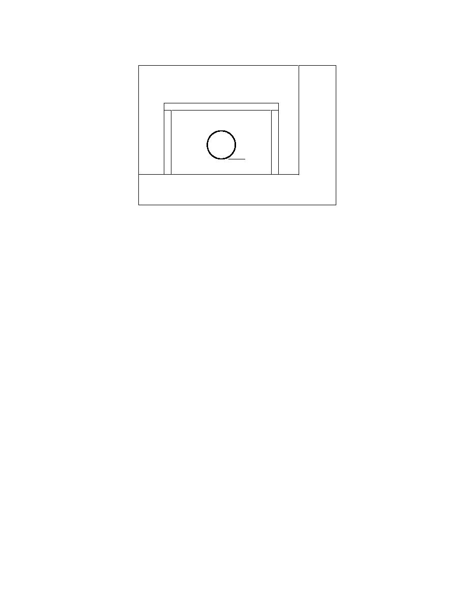
Figure 6. Initial design configuration used at Wentworth Street.
Bottom of pipe was placed at 0.91 m (3 ft) in this design. Top of
insulation was 0.225 m (9 in.) below surface.
string was installed above an uninsulated 0.2033-
In the initial design investigations for Went-
m (8-in.) pipe on 2nd Avenue, buried about 2.13
worth Street, a pipe depth of 0.91 m (3 ft) sur-
m (7 ft) deep, to record temperatures from the
rounded by ledge to the surface was assumed.
surface down to the pipe. An immersion TC and a
This physical configuration, shown in Figure 6,
flow meter were also installed in the pipe to
gave a conservative design arrangement, i.e., the
record water temperatures and flow rate. The un-
highest expected thermal conductivity, to verify
insulated water line on 2nd Avenue was part of a
the system performance in a thermally demand-
larger loop and thus gave water temperatures in a
ing shallow burial installation.
part of the distribution system that would have a
The design thermal boundary conditions used
higher water flow than the dead-end line on
the cold design year surface temperatures at the
Labossiere. This would help assess the differenc-
top of the mesh along with the measured 2nd
Avenue water temperatures, with 1.5C added to
es in water temperature for two different loca-
tions in the distribution system and determine
them, to simulate slightly warmer water than at
baseline data around an uninsulated pipe. The
Labossiere. The geothermal heat flux boundary
data also served as a backup for and a compari-
condition was at the bottom of the mesh at 10-m
son with the surface and air temperatures gath-
(32.8-ft) depth in all the runs.
ered on Labossiere Street.
To assess the time to freeze, the water flow was
shut off (the temperature boundary condition at
Wentworth Street
the pipe was removed) at two different times cor-
The second insulated pipe section was con-
responding to the time of minimum top surface
structed on Wentworth Street. Based upon the
temperature (MTT) and the time of minimum
good agreement between the numerical model
water temperature (MWT), and the time until the
0C isotherm touched the pipe was recorded. The
and the data gathered from Labossiere Street, the
failure criterion for the shield design was
design runs showed that if the water was shut off
changed to allow the pipe to reach 0C and to as-
at MTT, it was 290 hours before the 0C isotherm
sess the length of time it took to do so. Warmer
arrived at the pipe, and at MWT, 27 hours passed.
temperatures were expected in the pipe at Went-
The maximum frost penetration for this simula-
worth from information provided by the water
tion was approximately 2.1 m (6.9 ft).
works regarding the source of the water. It was
This design was acceptable to provide freeze
also expected, from test explorations at the site,
protection to the pipe, but there was some con-
that the pipe would be resting on ledge rather
cern about possible surface icing on the street
than buried directly in it. Thermally, this is a
above with the insulation so close to the surface
much better situation than at Labossiere Street.
(0.2246 m [8.8 in.] in this case). The issue of sur-
6


 Previous Page
