configuration around the pipe, or change the
burial depth, until the results are satisfactory.
Once a successful shield design is found, then an
economic analysis can be performed to see if the
added cost of the shield is less than the cost of
burying the pipe deeper.
NUMERICAL MODEL
In this project, a CRREL-developed finite ele-
ment program with a phase-change algorithm
was used to design the frost shield. It should be
emphasized that any FE program with an accu-
rate phase-change capability should be adequate
for designing.
The designer uses the dimensions of the pipe,
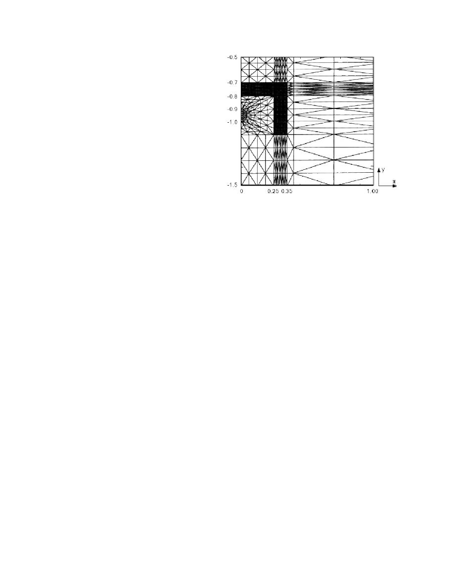
shield, and surrounding soils to create an FE Figure 2. Finite-element mesh showing mesh refinement
mesh that models the physical configuration of necessary for insulation and pipe.
the desired shield and pipe. This mesh consists of
a series of triangular elements arranged in zones
that depth does not vary with the surface temper-
that accurately represent the design being stud-
atures. The bottom boundary condition is set as
ied. The density of the element spacing is depen-
the average geothermal heat flux of 0.063 W/m2
dent upon the thermal gradients expected in the
(Lunardini 1981). This is theoretically the amount
zone. There is a nodal point at every line intersec-
of heat flowing up from the center of the earth.
tion in the mesh. It is at these nodal points where
The top boundary condition is the surface tem-
the temperatures are calculated during the simu-
perature present at the location being modeled.
lations. A vertical line of symmetry is used
In a design situation, this would probably be the
through the center of the design to reduce the
coldest expected surface temperature at the pipe-
number of elements and thus modeling time and
line location.
resources. Figure 2 shows a portion of a mesh
A distinction should be made between air tem-
used to model an inverted-U insulation shield
peratures and surface temperatures. Air tempera-
around a pipe. In the figure, the darker area is the
tures on average tend to be cooler than surface
insulation. Further information on FE modeling
temperatures, at least in New England. The de-
can be found in any textbook on the subject (see,
signer could choose to use air temperatures for
for example, Segerlind 1984).
design considerations, or these air temperatures
The thermal and physical properties of each
can be adjusted to surface temperatures through
material in the mesh are input to the program via
the use of n factors that adjust for the effect that
a materials file. The properties needed in the pro-
surface material, radiation, and other heat trans-
gram for each material are: thermal conductivity,
fer modes have upon the surface temperature
density, specific heat, latent heat, and phase-
(Lunardini 1981).
change temperature (if required).
In addition to the edge boundary conditions, it
Along with the physical configuration and
is necessary to add a boundary condition to
material properties, the mesh needs boundary
define the heat coming into the shield from water
conditions at the edges. The left and right sides of
flowing within the pipe. In the modeling, this
the mesh are set as zero heat flux boundaries.
temperature is used during the first step to com-
This in essence defines anything beyond the
pute the correct mesh temperatures under the
edges as being thermally identical to the thermal
influence of all the boundary conditions. This
conditions present at the edges. This is certainly
step is necessary to correct any temperature
true at the line of symmetry, and the mesh is ex-
errors caused by start-up error. Initially, every
tended out to 4.5 m (14.8 ft) wide to ensure the
nodal point in the mesh must have a temperature
outside boundary meets this criterion. The mesh
assigned to it, and frequently a constant tempera-
extends to a depth of 10 m (32.8 ft), which is a rea-
ture is used throughout. This would not be the
sonable approximation of the depth of zero annu-
case in reality, since the nodes near the surface or
al temperature amplitude, i.e., the temperature at
near the pipe would be influenced more by the
3


 Previous Page
