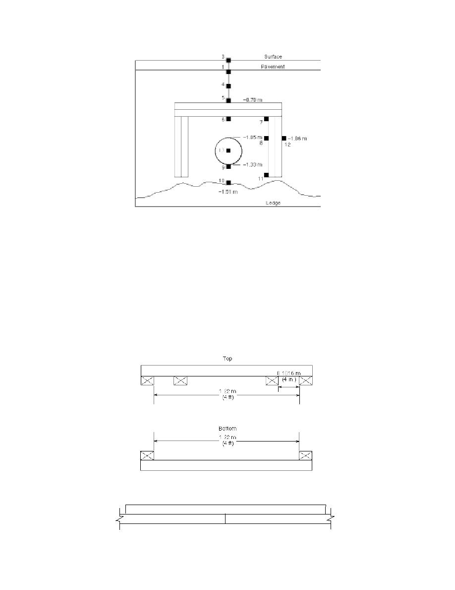
Figure 8. As-built configuration on Wentworth Street show-
ing thermocouple locations as small squares. Bottom of pipe at
test site was about 1.33 m (4.4 ft) deep with top insulation
board about 0.7 m (2.3 ft) below surface.
boards to hold them in place during construction
up to the level of the top of the shield side walls
(Fig. 9), and all the shield joints were staggered
and had been compacted, the excess was screed
(Fig. 10) to prevent thermal short circuits. The
off and the top horizontal boards were laid (Fig.
sand backfill was added evenly to the inside and
11). Care was taken to position the boards so there
outside of the shield to prevent the soil pressure
were no gaps between them and the vertical side
from collapsing the walls, and it was compacted
boards. These top boards were also staggered to
with a vibratory compactor. After the sand was
prevent thermal short circuits.
Figure 9. Jigs made from 2 4 lumber to hold insulation
during installation.
Figure 10. Staggered insulation board joints.
8


 Previous Page
