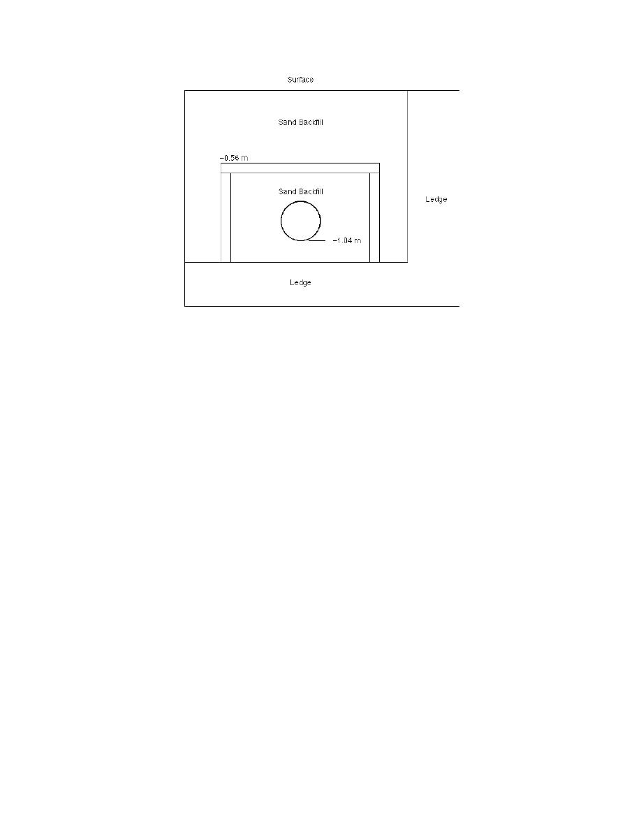
Figure 7. Final design configuration used at Wentworth Street.
Here bottom of pipe is 1.04 m (3.4 ft) deep and top insulation
board is 0.56 m (1.8 ft) below surface.
inverted-U shield was again placed over the pipe,
face icing is discussed in the Conclusions section.
A depth of at least 0.508 m (20 in.) below the sur-
this time only 0.1016 m (4 in.) thick. The total
face for the insulation was acceptable to all par-
shield width was 1.2 m (4 ft), and the total height
ties, and further design runs were performed.
was 0.71 m (28 in.). The shield was also construct-
The new design configuration was as shown in Fig-
ed using two layers of 0.051-m- (2-in.-) thick, 1.22-
2.44-m (4- 8-ft) SSE boards of SP-Formular
ure 7. Here the pipe depth is 1.04 m (3.4 ft) with a
0.1016-m- (4-in.-) thick shield. This put the top in-
250 extruded polystyrene foam insulation. As at
sulation board 0.56 m (1.8 ft) below the surface.
Labossiere, the trench excavation was backfilled
The time-to-freeze assessment showed times
with sand. Figure 8 shows the general shield and
of over 200 hr (the simulation was ended before
pipe configuration along with the TC locations
the pipe reached 0) from MTT and 35 hr from
for monitoring the temperatures.
MWT. The MWT time was an increase of 8 hr from
The new pipe was tied into an existing line at
the 0.91-m (3-ft) pipe depth tried earlier.
Cascade Street, where there were several interfer-
It was felt that the worst-case physical scenario
ing sewer lines and there was ledge near the level
on Wentworth Street would be as modeled above,
where the pipe had to be laid to clear them. Be-
i.e., if there was actually ledge to the surface
cause of this interference, the water works decid-
when it was expected to be down at about the
ed to lay a few sections of pipe before starting a
0.91-m (3-ft) depth. On this basis, it was decided
complete shield. Insulation boards were laid hor-
to install a 0.1016-m- (4-in.-) thick shield around
izontally over this first section, with about 56.1 m
the pipe.
(184 ft) of the 86.5-m (284-ft) pipeline getting a
full inverted-U shield.
The pipe and shield installation went very
Shield installation
similar to the Labossiere Street installation de-
Wentworth Street runs uphill at a slope of
scribed in Coutermarsh (1997), except most of the
about 6% between Cascade Street and Williams
Street in Berlin, N.H. The 0.2032-m- (8-in.-) diam-
digging was in the parent material rather than
eter ductile iron pipe was buried at depths to
ledge. The excavation was taken down to about
about 1.33 m (4.4 ft) on top of some existing ledge.
the level of the existing ledge, and approximately
The parent soil down to the ledge is a gravelly
0.1524 m (6 in.) of medium clean sand was put in
sand with an appreciable amount of fines. Since
the bottom for a pipe bed, with the pipe and shield
the actual ledge was deeper than had been antici-
constructed on this. Sand was used as a backfill
pated during the modeling, this was a more con-
around and in the shield. Wooden jigs were again
servative design than was probably necessary. An
used on both the top and bottom of the insulation
7


 Previous Page
