Direction of Travel
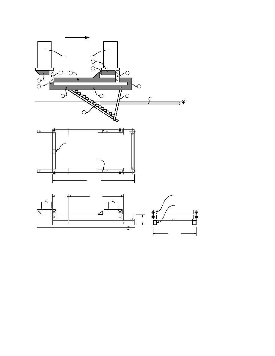
Figure 8. Model supporting platform. Items numbered in this
Carriage I-Beams
sketch are described in the text.
2
4
3
1
3
2
6
6
8
5
9
Ice Sheet
7
5000 lb Load Cell
(3 locations)
7500 lb Load Cell
(2 locations)
Figure 9. Model support system, in which the locations
of five load cells are shown.
10 ft -0 in.
Wall Box
2 ft -0 in.
6 ft -8 in.
(6 4 3/16 in.)
Wall Box
(7 5 5/16 in.)
1 ft -3 in.
5 ft -3 in.
that the model was partially submerged in the ba-
(9). By adjusting the length of the two steel bars,
sin (Fig. 8). Figure 9 shows the engineering draw-
we could change the slope of the model riprap sur-
face. We could set three slope angles, 18, 27, and
ings of the frame. We suspended the upper frame
34 from the horizontal, corresponding to vertical
(1) from steel box sections (2), which were bolted
to the carriage, with the help of four bar linkages
to horizontal distance ratios of 1V:3H, 1V:2H,
(3) so that it could freely swing back and forth and
1V:1.5H , respectively.
allow transmission of horizontal forces on the mod-
All load cells were calibrated to maximum ca-
el bank through two load cells (4) installed on the
pacity using standard calibration load cells prior
carriage. We supported a lower frame (5) under the
to the test program. After installing the test fix-
upper frame (1) through three vertical load cells (6).
ture under the carriage, we calibrated the load
Figure 9 also shows the location all load cells. We
measuring system, by applying a known load
installed the model bank (7) on the lower frame (5),
through another calibrated load cell, and com-
as shown in Figure 8. We supported one end of the
pared the known load to the sum of horizontal
model riprap frame (7) at a pivot point (8) on the
and vertical forces measured by the load cells in
lower frame (5) and the other end on two steel bars
the model.
7


 Previous Page
