Setup
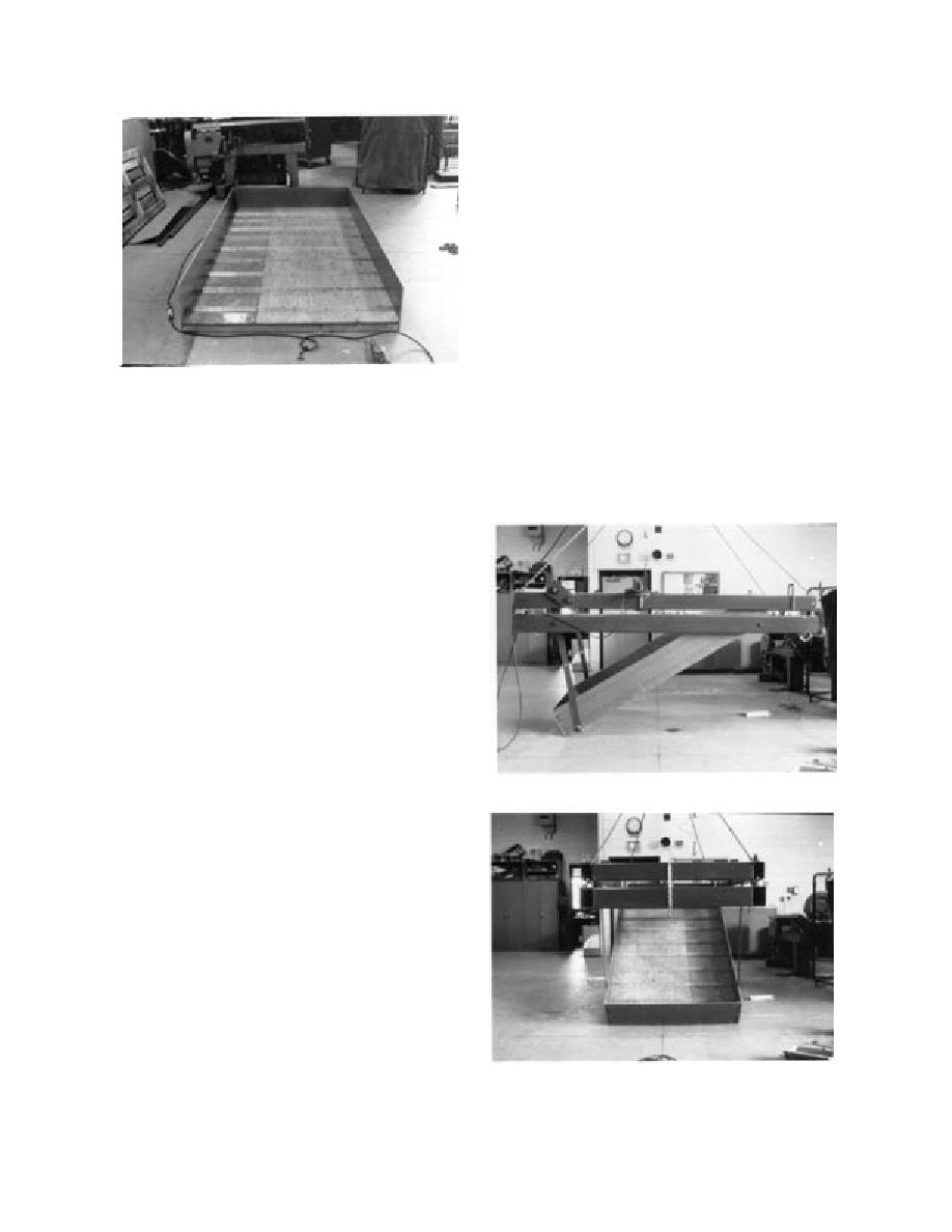
Figure 6 is a photograph of the aluminum box
in which we built each model riprap bank. It was
1.32 m (52 in.) wide and 2.44 m (96 in.) long. We
attached sides to the box to confine the sand bed,
filter, model riprap and ice in the model area dur-
ing a test. We left the top side of the model bank
open so that the ice reaching the top end during a
test could fall into the basin. We made the bottom
of this box with plywood reinforced with angle
iron, and we attached 25-mm- (1-in.-) 25-mm-
(1-in.-) aluminum angles to the plywood surface,
extending from side to side.
We installed the box containing the model riprap
Figure 6. Aluminum box used for model riprap bank.
in a supporting platform (Fig. 7), which enabled
us to measure the horizontal and the vertical forc-
es on the bank during the tests. Figure 8 shows a
model riprap, 2) to measure the forces generated
schematic drawing of a two-tiered frame, which
during the iceriprap interaction during the tests,
supported the model riprap bank. We installed the
and 3) to determine the conditions when ice shov-
whole assembly under the main carriage beams so
ing damages a riprap armor. In this report, we de-
scribe the experimental apparatus and procedure
used to simulate a riprap-protected sloping bank
being impacted by model ice, present the data ob-
tained during the 35 tests, and discuss the results
and their implications on design criteria for riprap
protection in ice-affected areas. The focus of this
study is for situations in rivers and lakes in the
cold regions. Generally, a riprap frozen to the un-
derlying material will be less prone to ice dam-
age. We decided to keep the model riprap armor
in an unfrozen condition so that the results of this
study will be conservative for the riprap armor
frozen to the material underneath.
EXPERIMENTS
a. Side view.
We constructed a physical model of an inclined
riprap-covered embankment at a scale of one-
eighth the actual size, based on typical ice flex-
ural strength. To simulate ice shoving on a riprap
bank, we mounted the model under the carriage
spanning the refrigerated test basin of CRREL's
Ice Engineering Facility, and pushed it against ice
sheets grown in the test basin. We could vary the
slope of the model riprap surface to three particu-
lar values and change the size and the mix of rocks
for different tests. We installed load cells at ap-
propriate places in the supporting structure of the
model to measure the horizontal and the vertical
forces generated as a result of interaction between
b. Front view.
the ice and the riprap. Thirty-five tests were con-
ducted to model various combinations of the vari-
Figure 7. Box and the supporting platform prior to their
ables.
installation under the carriage.
6


 Previous Page
