Ic
e
Bl
o
ck
s
Z
Force from
Ice Blocks
Floating Ice Sheet
Force Pushing
Reaction
the Ice Sheet
Force
α
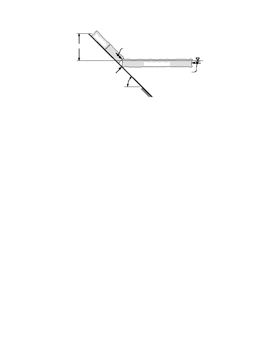
Figure 5. Sketch of forces acting during ice interaction with a sloping
surface, where α is slope angle from the horizontal and z is the height
of pushed-up ice blocks.
sis, Hopkins (1995) simulated onshore pileup and
the pressure on an individual rock can be as high
ride-up of an ice sheet moving against an inclined
as that to crush ice. The shear component can in-
surface. He compared the results of his simula-
troduce a rotation and dislodging of an individual
tion with measured values of forces and energy
stone if opposing moment cannot be developed
during a small-scale experiment. As part of this
from neighboring stones. To prevent such damage
study, he also attempted a two-dimensional, dis-
from ice, the individual rocks that make up the ar-
crete-particle simulation of ice action on a sloping
mor stone or riprap layers should be placed on the
surface protected by two layers of stones. The sim-
slope in such a way that the surface of the protec-
ulation showed movement of a few rocks until
tive layer is relatively smooth. This is contradicto-
they were embedded in an ice pile. Though this
ry to the design practice of riprap to resist wave
simulation looks to be promising, the two-dimen-
action, where a rough surface is intended to dissi-
sional aspect of this analysis is a limiting factor in
pate the wave energy.
establishing a relationship between the riprap
Croasdale (1980) presented a two-dimensional
damage and the extent of ice action. Small-scale
formulation of the forces that result from an inter-
experimentation is one of the means with which
action between a floating ice sheet and a sloping
we can study the ice effects on riprap armor in
structure, as shown in Figure 5. The horizontal force
terms of stone size, ice thickness, slope angle, and
against a sloping surface results in a vertical force
ice flexural strength and elastic modulus.
at the point of contact, which deflects the ice sheet
The purpose of this study is to assess the dam-
up. When the maximum stress in the ice sheet ex-
age to riprap protection by the shoving action of
ceeds the flexural strength, the ice sheet fails in
an ice sheet. The focus of this study is for season-
bending. The broken pieces of ice are pushed up
ally occurring ice on rivers and lakes in the cold
the slope and cause additional resistance to the
regions, such as the northern tier of the United
advancing ice sheet. Nevel (1983) has given a simi-
States. In those areas, it is possible for riprap to
lar, but more rigorous, formulation of ice failure by
have varying degrees of fixity to the bank during
bending.
a given ice impact event. The degree of attachment
In general, the ice sheet deflected up by the slop-
can range between two extremes: 1) when a riprap
ing surface fails in bending into large ice blocks,
is strongly attached to the bank by being frozen in
which may further break into smaller blocks as they
place, and 2) when a riprap is not frozen to the
move upward and over irregular surface of the
bank. Generally, a riprap frozen to the underlying
stones. Because of the nonsmooth surface of a rip-
bank will be less prone to damage by ice action.
rap protection system, a detailed analysis of inter-
Because ascertaining and simulating varying de-
actions between the ice blocks and the rocks is very
gree of fixity of a riprap to the bank is difficult, we
complex. The damage in a riprap armor takes place
chose to conduct the physical model test program
by removal and transport of stones by ice, and keep-
using the riprap in an unfrozen condition.
ing track of progressive damage is impossible in a
The objectives of this small-scale experimental
simple theoretical analysis (e.g., Croasdale 1980,
study are 1) to conduct small-scale tests of ice shov-
Kovacs and Sodhi 1980).
ing against a sloped surface protected with a
Using a two-dimensional, discrete-particle analy-
5


 Previous Page
