to establish monitoring stations with-
- temperature
Hydrolab H20
out setting stakes or foundations in
- depth
F
- salinity
the ordnance-bearing mudflat sedi-
- pH
ments; however, the platform's main
- dissolved oxygen
redox
task is to keep the datalogger and re-
Solar Panel
lated devices dry during the highest
Thermistor
- temperature
flood levels. Dataloggers were in-
Pressure Sensor - water depth
ISCO Sampler
stalled in NEMA plastic enclosure
Data Logger
- optical backscatter
boxes mounted on 2-in. (~5-cm) verti-
OBS
(turbidity)
cal steel pipes. Solar panels of 18-W
- water sampler
ISCO
output were fastened to the pipes
intake
above the dataloggers to recharge the
12-V external battery. Ultrasonic sen-
sors were also mounted on an arm
attached to the support pipe and aimed
downward towards the mudflat sur-
face, which was covered by a metallic
plate pinned to the ground.
An ISCO Model 3700 water sam-
pler was also mounted on the plat-
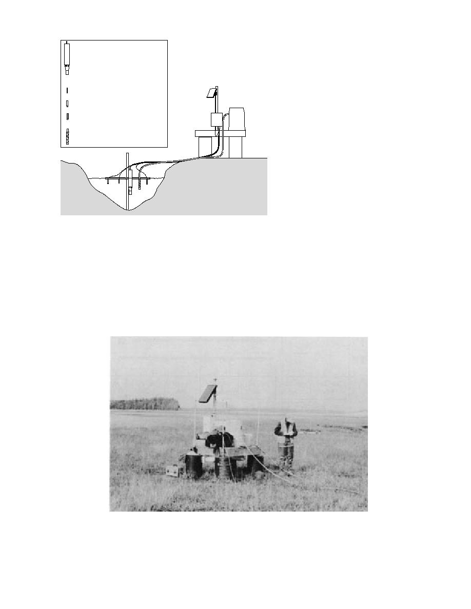
igure 18. Schematic of hydrostation showing layout.
form at each site, except B-Gully (Fig.
18). A tygon tube extended from each
sampler to an intake screen positioned on the
same crossbar bearing the electronic sensors. The
tically in 20-gal. (75-L) cans filled with concrete,
sampler was programmed to obtain 500-mL wa-
and the eyehooks mounted on the platform's
ter samples at specific intervals through the flood
wood frame lowered over them. Foam filled the
and ebb cycles. These samples were processed for
inner space of the deck framework and provided
TSS concentration using vacuum techniques and
flotation so that the platform could move verti-
45-m glass microfiber filters following proce-
cally up and down the steel pipes during tidal
dure 2540D in Standard Methods for the Examina-
flood and ebb (Fig. 19). The platforms allowed us
Figure 19. Platform and instrumentation measuring discharge characteristics at the
Bread Truck Gully location.
20


 Previous Page
