rotation about X axis, relative to reference target orien-
and deepening its inclination diminishes the first, low-
tation). In this case, given the reference antenna orien-
est mode and brings out the higher modes, ultimately
tation (Fig. 14), the incident E field is aligned with the
more strongly than the first. Given the dielectric con-
target. Although the same effects described below are
stant, this kind of pattern allows one to infer the target
generally apparent without normalization, for general-
length from the separation of the peaks/troughs in the
ity we scale the magnitude of the received signal by the
pattern. Previous investigators (Geng et al. 1999) have
demonstrated the existence of shape-dependent natural
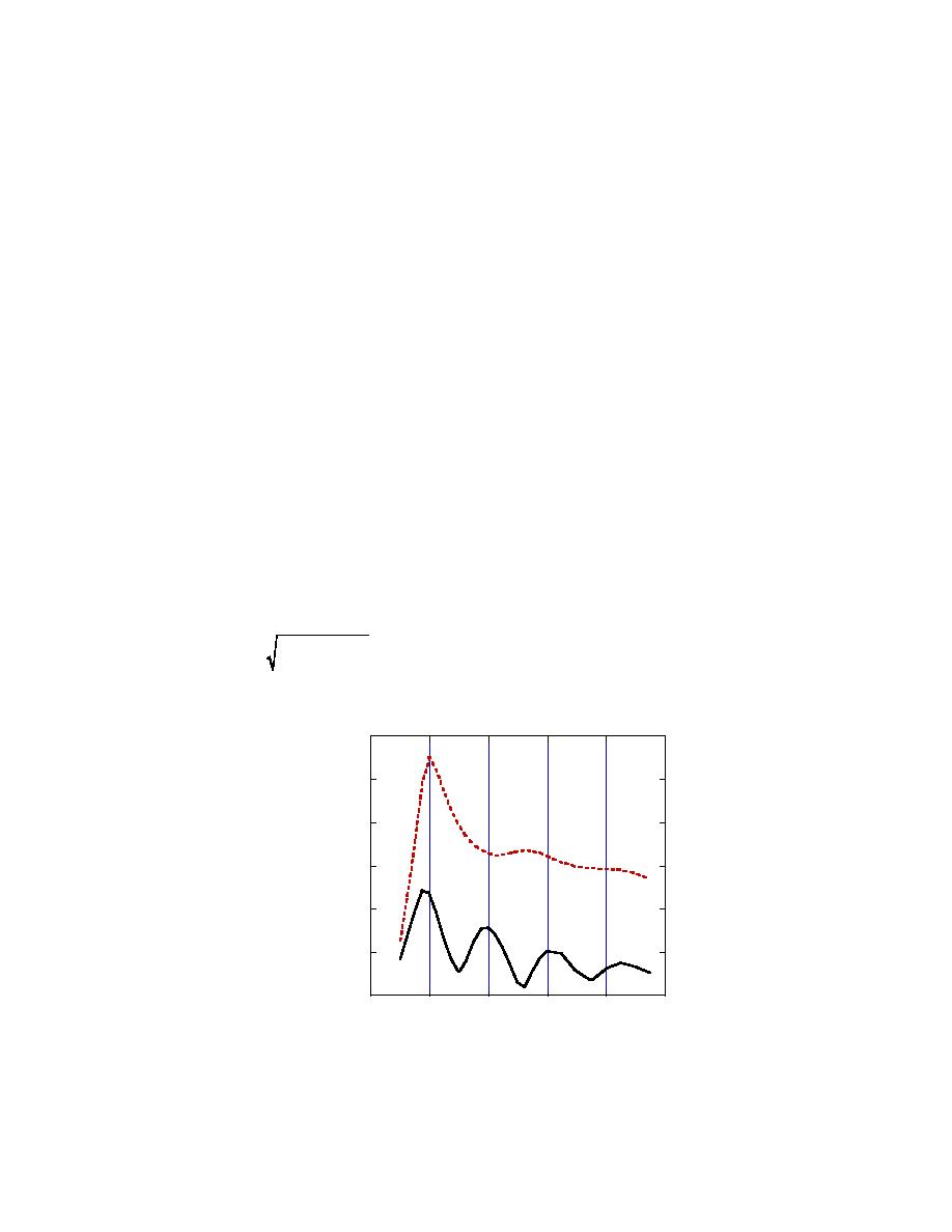
function of frequency. Figure 15 shows normalized
backscatter response across the band. The clear maxi-
from, metallic bodies of revolution (BORs). These cor-
mum occurs at 100 MHz where, given the dielectric
respond to electromagnetic "free vibration," after any
constant assumed (10.2 + i 2.8 103), the subsurface
forcing effects have died out, at frequencies less than 1
wavelength is almost exactly twice the target length.
MHz, consisting primarily of decay patterns. Here we
That is, the projectile responds most strongly when it
see what are in many ways comparable effects in the
can serve as a half-wavelength dipole antenna. The
radar frequency range, when responses are forced and
change in the target's cross-sectional shape along its
the resonant frequencies we seek are real valued.
As θx => 0 we lose the kind of amplitude pattern
axis does not appear to interfere significantly with this
effect.
in the previous two figures, but fortunately we gain
another, which adds basic information as long as θd <
Perhaps more revealing than this horizontal case,
90. The upper line in Figure 17 shows the normalized
similar scattering behavior is apparent when the target
scattered E field magnitude when the antenna is directly
is inclined further, even when it is rotated about the
above a level projectile (Za = 0). Both antenna and tar-
vertical (x) axis. The lower (solid) line in Figure 15
shows the effect of adding a 45 inclination (θd) to the
get are in the reference configuration (Fig. 14). The
target, keeping it in (x,y) plane. We see a clear succes-
lower line shows results for the same case but with the
sion of higher modes for higher multiples of L/(λ/2).
projectile inclined 45 (θd = 45, θx = 0) and the
This pattern persists for a variety of inclinations and
antenna is located at Za = 0.72. Both results are shown
rotations (Fig. 16), as long as the impinging radiation
vs. Re{k}a where a is the radius of the uniformly
travels longitudinally along the surface of the target to
cylindrical portion of the target. Basically, both of these
some degree. Here the "total" scattered field magni-
show most of the first cycle in the well-established
cyclical scattering cross-section pattern for a circular
2
2
| Ey | + | Ez | . Rotating the
tude Etot is defined as
cylinder, in the resonance region, under normal inci-
target back towards the reference orientation (θx = 0)
dence with transverse E field (Bowman et al. 1988).
0.3
0.25
0.2
θd = 0
|Ey|/Eo
0.15
0.1
θd = 45o
0.05
0
0
100
200
300
400
500
f (MHz)
Figure 15. Normalized scattered electric field above a projectile
surrounded by soil and oriented in the Y direction, as a function
of frequency.
24


 Previous Page
