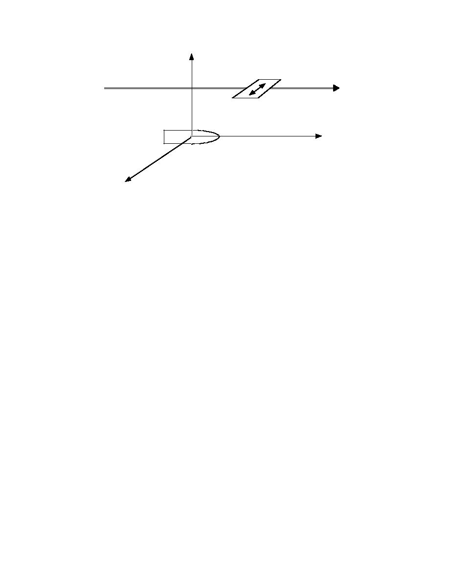
X
antenna
transect
line
Z
target
Y
Figure 14. Basic setup, with target below ground surface, in its reference ori-
entation. The fully polarimetric, orientable antenna is above it, at some posi-
tion on a survey transect line.
For received signals we assume that a horizontally ori-
equations, which underlie Huygen's principle and form
ented antenna records the computed Ey and Ez, with-
the basis for describing all electromagnetic wave phe-
nomena. Any input to our problem that violates those
out applying the antenna pattern to its receiving char-
equations to some degree thwarts our ability to check
acteristics.
the ultimate output for electromagnetic consistency, e.g.,
energy conservation. Beyond this, the antenna model
MODELING RESULTS
contains two basic features in common with the actual
antennas in frequent use: broader, smoother pattern in
the H plane, which is usually coincident with the sur-
In what follows, the survey transect is always 0.7 m
vey transect direction; and beamwidth that depends on
above the target, as if along a ground surface. We some-
frequency in the manner of a current sheet or set of
times consider cases in which the antenna is variously
aperture fields. In practice, numerical computation of
rotated relative to the target axis or relative to the
the incident H values at each element centroid was a
transect direction. The latter rotation was not enlisted
very minor burden, in terms of both programming and
systematically in the field measurements at JPG dis-
CPU time.
cussed here. However, it offers insight into possible
Because the fields radiated by the antenna are not
target scattering behavior when the target is arbitrarily
planar, we will indicate antenna orientation rather than
oriented relative to the incident field, which was likely
speak of the polarization of the incident field. We al-
to be the case during a survey. Some of the features in
ways assume that currents run in its long direction
the field profiles push questions to the fore: how can
with the same distribution relative to the antenna.
the target response from points not above the target
Especially because we are surveying at shallow depths,
arrive relatively early in time, then appear to fade some-
the incident field is nonuniform in both magnitude
what, then return to higher amplitude? Rotations of the
and direction over the target geometry. In practice,
target relative to the antenna are seen below to impose
the orientation of the E field over most of the
interesting spatially and frequency dependent patterns
target is reliably in the E plane of the antenna. In the
in the scattered signal. Relative rotation of antenna and
(x,z) plane, which contains the transect line, the most
target also suggest ways of discriminating hard cases.
consistent E field orientation results from the reference
First we examine scattering responses when the pro-
antenna orientation in Figure 14: the transmitted E field
jectile is level, beginning with it oriented in the Y
is always normal to that plane, parallel to the Y axis.
23


 Previous Page
