different frequency content in the beam and different
one with parallel and the other with perpendicular an-
incidence angles would cause different responses to
tenna orientation; these results can then be combined
for a completely general polarimetric characterization.
become relatively more prominent. A key to successful
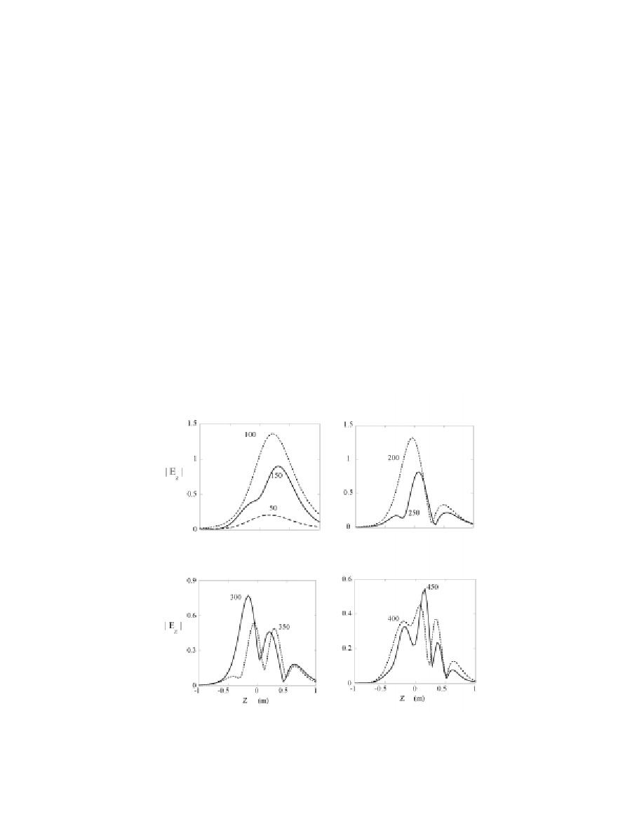
Figure 18 shows a progression over increasing fre-
discrimination will be to identify various target char-
quency, from more or less a single event (peak) at 100
acteristics in stages, starting with things like depth and
MHz, through two and three events at 200 MHz and
orientation, and then use these to calibrate subsequent
300 MHz, respectively, and four events at 400 MHz.
treatment of the data.
That is, the number of peaks/events corresponds to the
Examination of the broadband response along the
number of half wavelength multiples in the target length.
transect can reinforce the above target length estima-
In this case, the Ez backscattered field component is
tion, while adding information about the variation of
its geometry along its axis. Figure 18 shows
generated by the tendency of the target to induce cur-
backscattered Ez amplitudes along the transect when
rents preferentially in the general direction of its long
the projectile is inclined at 45 with its nose up (i.e., θd
axis. In fully polarimetric surveying, this tendency, to-
= 225, θx = 0). This orientation does indeed occur in
gether with the circumferential creeping wave phenom-
reality, though it is less common than a nose-down sub-
ena illustrated in Figure 17, produces characteristic and
surface rotation. In any case, our purpose here is pri-
very revealing induced ellipticity and depolarization in
marily to study the fundamental effects of target orien-
the scattered signals (O'Neill et al. 1999).
tation, whatever it may be. In this and all subsequent
The pattern in Figure 18 is altered in certain inter-
figures, scattered field values are not normalized. To
esting details when the projectile direction is reversed,
provide the most general illumination, the antenna has
that is, with the same overall orientation but with its
nose down and tail up (θd = 45, θx = 0). Figure 19
been rotated horizontally 45 so its axis is oblique to
the transect direction, producing an incident E field nei-
evident that the upward pointing flattened end of the
ther aligned with nor transverse to the target axis. In
target has a prominent influence in changing the pat-
practice this can be accomplished by two measurements,
frequencies, when the projectile is inclined at 45 with nose up (θd = 225,
26


 Previous Page
