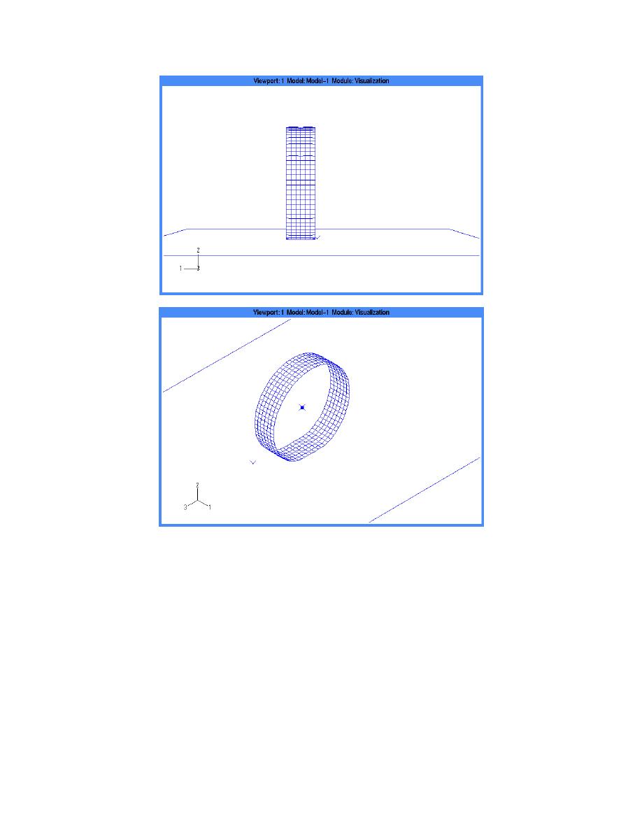
b. Fine (6 72) mesh.
Figure 42 (cont.). Shoop-Darnell tire model.
The analysis is done in three steps: inflating the
structed of linear, hybrid continuum elements
tire to the desired pressure, vertically loading it based
(C3D8H), with constant pressure (simulating the
on the vehicle's weight, and rolling it along the road
nearly incompressible nature of rubber). The result is
by translating its centerpoint while allowing free rota-
a reasonable approximation of both the structural
tion about its axis. The creation and seating of the
behavior and the contact patch. The model is con-
bead are accomplished by multi-point constraint and
structed using the cross section shown in Figure 43,
fixed displacement of the first four rings of nodes
repeated every three degrees around the axis of the
closest to the wheel rim. During the inflation and
hub (creating 120 cross sections). For most of the
loading steps, no friction is included on the contact
simulations the tire model was cut in half using a
surface. Variations of the analysis include a static
vertical symmetry plane along the longitudinal axis.
rolling step, a dynamic rolling step, and changes in
The wheel mass is represented by one mass element
the definition of the shell element local coordinate
and one rotary inertia element located at the wheel's
system.
centerpoint on the symmetry plane.
31


 Previous Page
