Table 7. Bending stiffness of tire sections.
Width
Length
Thickness
EI
(N m2)
(cm)
(cm)
(cm)
Sidewall section A1
5.2
3.3
1.3
0.1564
Sidewall section A2
5.2
2.0
1.3
0.0287
Sidewall section A1+A2
5.2
5.3
1.3
0.1521
Sidewall section B
5.8
6.1
0.6
0.0459
Sidewall section C
7.0
2.1
1.1
0.0172
Lateral tread section
7.0
16.5*
1.7
0.1550
(0.9 w/o tread)
Longitudinal tread section
12.5
27.2
1.7
0.5137
(0.9 w/o tread)
Shoulder
33.5 cm
along tread
* 23.4 cm including shoulders
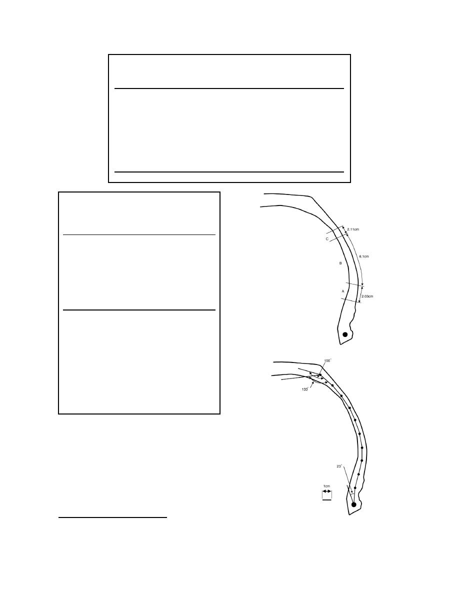
Table 8. Properties of sidewall elements and
tire model components.
Curvature
Stiffness per unit
Element
(1/m)
width (N m)
1 (Bead end)
0.01
2 (rigid)
2
6.76
1.5
3
7.63
0.15
4
9.95
0.04
5
8.62
0.04
6
9.71
0.04
7
9.01
0.04
8
9.09
0.15
9
14.49
0.5
10 (Tread end)
17.54
1.0
Total length of sidewall = 16.1 cm, each element L = 1.6
cm
Tread attachment angle = 133
Rim attachment angle = 23
Tread diameter to end of last sidewall element = 72.5 cm
Tread diameter to center of belts = 69.5 cm
Rim diameter to first sidewall element = 41.6 cm
Tread longitudinal shell flexural rigidity for unit section
width, E1I = 4.1261 Nm2
For 1.11-mm shell thickness, E1 = 3.62 1010 N/m2
Tread lateral shell flexural rigidity for a unit section width,
E2I = 2.259 Nm2
For 1.11-mm shell thickness, E2 = 1.98 1010 N/m2
metry, and sidewall and shoulder stiffness. These are
listed at the bottom of Table 8.
For the elements representing the tread, the shell
stiffness was calculated with E1 being along the tread
in the longitudinal direction and E2 being across the
tread in the lateral direction. An equivalent shell
thickness of 1.11 mm was used in the model since
this was found to yield a reasonable hoop stiffness
based on measured changes in circumference with
inflation pressure.*
Figure 41. Tire geometric parameters for
* Personal communication with I. Darnell, University
the sidewall model.
of Michigan, 2000.
29


 Previous Page
