d2
Tread
θ tread
Tread
Tread Reference
Spring
Angle (γ)
Sidewall
Length
Side
Radius of
Wall
Curvature
s
Rim
Spring
d1
Bead Reference
Angle (θ)
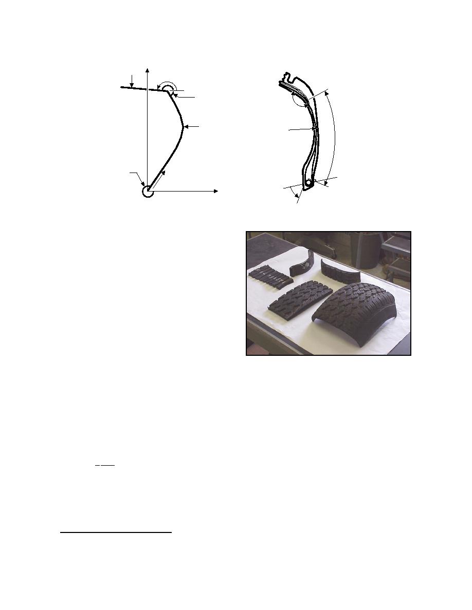
Figure 39. Construction elements of the Darnell tire model. (After Darnell et al. 1997.)
The Darnell tire model was validated for a Ford
Taurus tire for lateral forces and deflection on a
smooth surface and while rolling over an angled ver-
tical step (Darnell et al. 1997) and for slip angle and
aligning moment.* The model results sufficiently
mimic tire behavior while being computationally
efficient, indicating its potential for simulations of a
tire on deformable terrain. Some alteration in the
sidewall model may be necessary to account for the
interaction of the sidewall with the deformable terrain
if sinkage is substantial.
The same tire used to gather motion resistance
data on various terrain (snow, freezing and thawing
ground) was cut into four sections: sidewall, lateral
Figure 40. Cut tire sections used to determine
tread, longitudinal tread, and shoulder (Fig. 40). The
composite tire properties.
sidewall was further dissected into smaller sections
for future work expanding the sidewall model. The
I
sections were tested in the laboratory to determine
the beam stiffness (EI) by clamping an end of the test
section onto a workbench to form a cantilever beam.
Deflections were measured for a range of loads, and
stiffness was calculated using the equation for a can-
tilever beam with a point load on the free end:
1 Wl 3
ymax =
(25)
3 EI
where ymax = maximum deflection at the free end
of the beam
W = applied load
E = Young's modulus of the beam
* Personal communication with I. Darnell, University
of Michigan, 1997.
28


 Previous Page
