M = slope of the critical state line in the pq
plane, which controls the shape of the
yield ellipse
recoverable strain
ν = Poisson's ratio.
The following sections explain the Drucker
Prager cap model and the crushable foam model in
more detail.
Modified DruckerPrager cap model
For the modified DruckerPrager cap model used
in this study, the yield surface is a modified von
Mises yield (i.e., the material constant K = 1.0),
which is circular in the deviatoric plane (Fig. 9). In
the pt plane the yield surface has two major seg-
ments: the DruckerPrager shear portion of the curve
(analogous to the MohrCoulomb line) defines shear
deformation, and the cap portion of the surface de-
fines the intersection with the pressure axis (Fig. 17).
The following equations define the yield criteria in
each section of the yield surface.
For the DruckerPrager shear or distortional fail-
ure:
Fs = t - p tan β - d = 0 .
(12)
For the cap region of compactivedilatant failure:
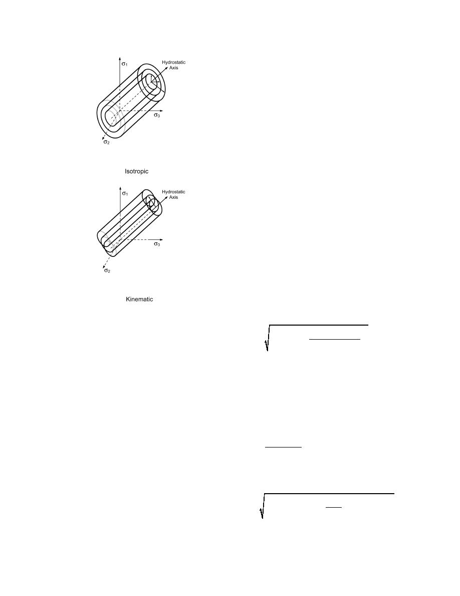
Figure 16. Isotropic and kine-
matic hardening. (After Shen
and Kushwaha 1998.)
2
Rt
( p - pa )
2
Fc =
+
(1 + α - α / cos β)
(13)
Parameters
A relatively small number of parameters are
-R (d + pa tan β) = 0
needed for these material models. Although more
detailed models may provide a more accurate solu-
where α is a transition parameter, ranging typically
tion, the parameters needed to define the model
from 0.0 to 0.05, that smooths the transition between
become prohibitively numerous and are often un-
the shear failure and the cap failure, R is a material
available. The objective of any model is to capture
parameter controlling the cap eccentricity, and pa
the most important material behaviors without being
defines the evolution of the cap along the pressure
unduly cumbersome. The following descriptions of
axes (via pbεvol hardening law) according to
the material parameters are based on the models as
implemented in ABAQUS (HKS 1998). Additional
pb - Rd
information on soil plasticity and critical state soil
pa =
.
(14)
(
1 + R tan β)
mechanics is given in Wood (1990).
The model parameters used in this study are:
The transition between the shear and the cap fail-
d = DruckerPrager material cohesion
ure is
β = DruckerPrager material angle of friction
λ and κ = slopes of the loading (compression) and
2
α
( p - pa )
(d + pa tan β)
unloading (elastic) lines in the compression
2
Ft =
+ t - 1 -
cos β
plane as indicated in Figure 14. This hard-
ening or softening of the material can also
-α (d + pa tan β) = 0 .
be defined in a piecewise manner (Fig. 15).
(15)
10


 Previous Page
