tion that the subgrade soil is of a sufficient depth,
gregate cover of 0.15 m (6 in.).
Hmin, to allow the plastic zones associated with
Thus, the Giroud and Noiray (1981) technique
ultimate bearing capacity to develop. For the stress
is not generally applicable to thawed (or weak)
distribution assumed by Giroud and Noiray
layers less than 0.4 m (16 in.) thick, and the same
(1981), this amounts to
is assumed for the current U.S. Army design tech-
nique. If a geotextile is used and the full plastic
zones do not develop, the tension in the geotextile
B + 2h tan α
Hmin =
(6)
will not be fully mobilized. However, assuming
2
that the subgrade soil underlying the thawed soil
is stronger than the thawing soil, the support re-
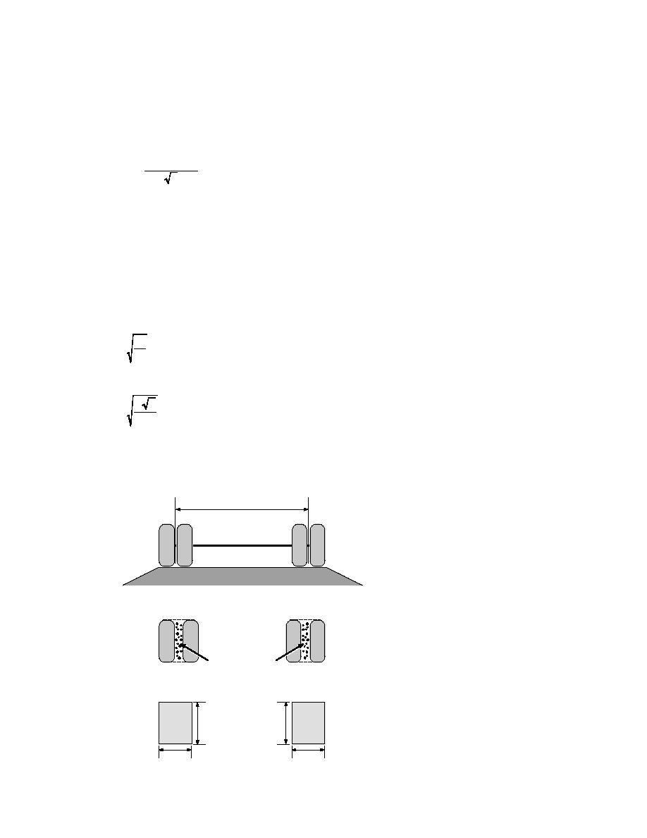
where B is the width of the loaded area at the soil
quired of the geotextile will also be less than if the
surface (Fig. 9b), h is the thickness of the aggre-
subgrade were uniformly weak; and, therefore (as
gate layer, and α = (π/4) (φ/2), where φ is the
mentioned above), designing for reinforcement
with geotextile would be conservative. When the
friction angle of the base course expressed as ra-
thawed layer is so thin that full plastic zones can-
dians (Fig. 10). Giroud and Noiray (1981) assumed
the value of tan α to be 0.6. Assuming a dual-tired
not develop, the geotextile may provide impor-
tant separation between the thawing soil and the
truck with an axle load, P, having tire pressures,
aggregate that will likely lead to longer use of the
Pc, the width, B (m), of the wheel load is given by
road without maintenance.
(Giroud and Noiray 1981)
Other assumptions pertaining to the geo-
synthetic include that
P
B=
for off-highway trucks and
Pc
1. The geotextile does not fail,
2. The shape of the deformed geotextile consists
of parabolas (Fig. 8, bottom),
3. The aggregate will not slide along the geotextile
P 2
B=
surface,
for on-highway trucks.
(7)
Pc
4. The elongation, or strain, is uniform along the
entire length of the geotextile, and
5. The modulus of the geotextile, K, used in de-
Table 2 presents values for Hmin for a minimal ag-
e
(a)
Aggregate
Figure 9. Definition of tire contact
area for dual tires (top), and equiva-
Ac
lent contact area used in analysis
(Giroud and Noiray 1981) (bottom).
(b)
(For single tires, L and B refer to
Soil mechanically
associated with
length and width of single tire print,
adjacent tires
respectively.)
L
L
B
B
10


 Previous Page
