in.
m
50
1.2
40
1.0
0.8
Without Geotextile
30
0.6
20
With Geotextile
0.4
10
Contact Pressure = 55.2 kPa ( 80 psi)
0.2
Contact Pressure = 103.4 kPa (150 psi)
0
0
0
10
20
30
40
50 kPa
Undrained Shear
Strength
psi
0
1
2
3
4
5
6
7
CBR
0
0.25
0.50
0.75
1.00
1.25
1.50
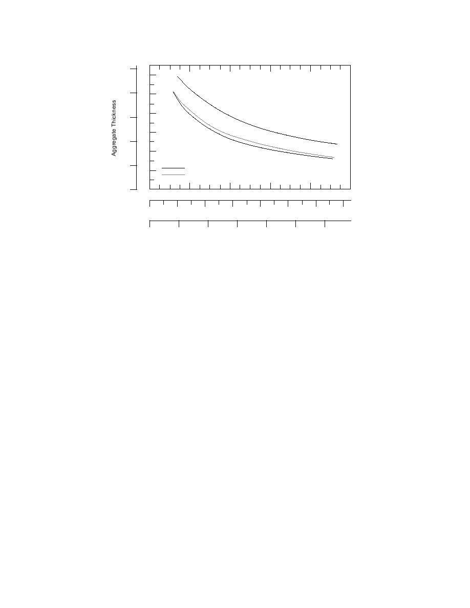
Figure 5. Design aggregate thickness chart for a 88.95-kN (20,000-lb) wheel load. (From
Barenberg et al. 1975.)
further loading of the same magnitude caused
However, localized plastic strains that can cause
negligible additional deformation. The unre-
localized shear failure begin at
inforced systems deformed progressively with
q ≈ πc .
repeated loading.
(3)
Barenberg et al. (1975) constructed design charts
for aggregate thickness vs. soil strength by assum-
Barenberg et al. (1975) conducted laboratory
tests (two dimensional, cyclic loading) with a
ing that the allowable pressure at the subgrade is
3.3c without geotextile and 6c with geotextile (Fig.
geotextile (Mirafi 140) placed between crushed-
5). Stress at the subgrade was calculated by using
rock aggregate and a saturated clay subgrade.
Boussinesq stress distribution beneath a circularly
Stress levels on the subgrade were estimated by
loaded area (Newmark 1942). The contact area, A,
using a Boussinesq stress distribution beneath a
was determined by dividing the wheel load by the
circularly loaded area (e.g., Newmark 1942), and
contact pressure. The radius, r, needed for deter-
ratios between the calculated subgrade stress and
measured soil strength were developed. The al-
mination of the stress at the subgrade surface, was
obtained from A = πr2.
lowable stress with geotextile on the subgrade
surface was
Barenberg et al. (1975) did not consider tensile
modulus or strength (or any mechanical property)
σzallowable = 6c .
(4)
of the geotextile in developing their design
method. Furthermore, even though Bender and
However, without geotextile, this relationship was
Barenberg (1978) note that "a layer of aggregate
material is always needed on top of the fabric to
σzallowable = 3.3c .
(5)
anchor it so that the necessary tensile forces can
be developed in the fabric" (p. 66), neither the
These numbers are very close to the theoretical
minimum depth for anchorage nor the mechani-
values of general and local bearing capacity fail-
cal properties of the aggregate layer are specified in
ure (eq 2 and 3). In addition to the change in fail-
either Barenberg et al. (1975) or Bender and
ure mode from local to general bearing capacity
Barenberg (1978). The effects of traffic loading when
failure, the soil systems that contained geotextile
vehicle passes exceed 100 were accounted for by
reached a level of permanent deformation so that
Steward et al. (1977) by reducing the Nc values.
5


 Previous Page
