m
in.
1.0
35
Axle Load = 80 kN (18,000 lb)
0.8
Rut Depth = 0.2 m (8 in.)
30
Tire Pressure = 480 kPa (70 psi)
25
0.6
20
0.4
15
10
N = 100
0.2
N = 10
5
0
0
0
20
40
60
80
100
120 kPa
Undrained Shear
Strength 0
2
4
6
8
10
12
14
16
psi
CBR
0
1
2
3
4
m
in.
1.0
35
∆h for:
0.8
1 K = 50 kN/m
Axle Load = 80 kN (18,000 lb)
30
2 K = 200 kN/m
Rut Depth = 0.2 m (8 in.)
Tire Pressure = 480 kPa (70 psi)
3 K = 350 kN/m
25
0.6
20
0.4
15
10
3
0.2
2
1
5
0
0
0
20
40
60
80
100
120
140 kPa
Undrained Shear
Strength 0
16
18
0
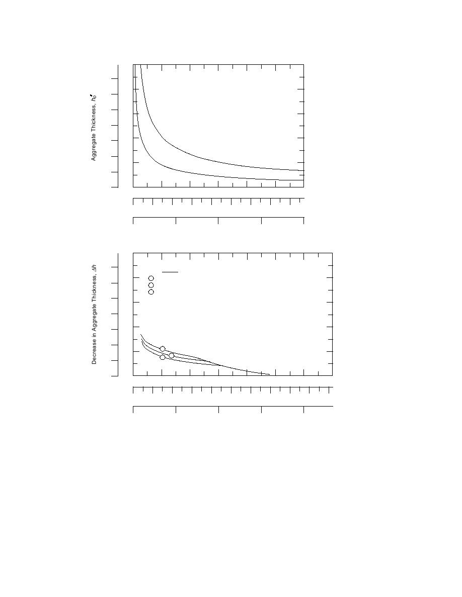
Figure 7. Aggregate thickness, ho′ (top), and reduction of aggregate thickness, ∆h (bottom),
resulting from use of geotextile as a function of soil cohesion for 8-in. rut depth. N is num-
ber of vehicle passes and K is tensile modulus of geotextile. (From Holtz and Sivakugan
1987.)
aggregate layer should probably be a minimum
m (10 in.). The difference results from how each
of 0.10 to 0.15 m (4-6 in.) to prevent damage to
method estimates stress at the subgrade; this is
the geotextile as discussed below.
discussed in Theory, below, and in Stress Distribu-
tion Through the Aggregate Layer in the comparison
Notice that for the same conditions without
of the Giroud and Noiray and Army methods.
geotextile, less aggregate is recommended by the
Although the total amount of aggregate required
Giroud and Noiray design method than by the
by the two design methods is different, approxi-
Army method--0.2 m (8 in.) compared with 0.25
mately the same aggregate savings are realized by
8


 Previous Page
