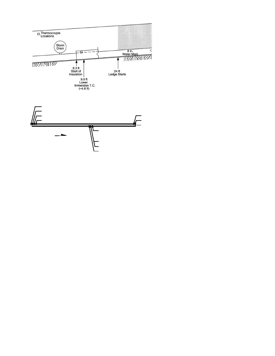
Figure 6. Storm drain location, immersion thermo-
couple, and the start of the insulated pipe section on
Labossiere Street.
0+00
0+09.9 TC1 (Immersion TC)
4+10 Immersion TC
0+15.0 Storm Drain
4+17 End of Pipe
0+19.6 Flow Meter
Pipe Centerline
2+46 Pipe Cable, Inside Center Cable, Side
Cable, and Outside Top Center Cable
N
Thermocouples
2+43 Offset 18 ft West, Control TC
Figure 7. Instrumentation layout along
2+39 Immersion TC
the pipeline.
2+31 Sewer Pipe Crossing
A section of pipe was laid on top of these jigs
insulation shield begins about 2.4 m (8 ft) past the
and centered in the ditch, after which the sides of
underdrain.
the shield were installed. It is important to pro-
The top of the new water line at the storm
vide even mating surfaces and to stagger the in-
drain is about 1.5 m (5 ft) below the surface. A
sulation joints to prevent a direct path for heat
backhoe was used initially to excavate for the
loss out of the shield. Three layers of the 5.1-cm
new line, as the ledge that was encountered was
(2-in.)-thick extruded polystyrene insulation were
relatively soft. We quickly ran into very compe-
necessary to get our final design thickness, so the
tent ledge, however, and the ditch line had to be
boards were staggered as shown in Figure 9. Any
blasted; a larger excavator was brought in to re-
slope changes were made gradually to avoid a
move the debris. We tried to clear the rock down
gross vertical misalignment of the side boards.
to 1.8 m (6 ft) deep with a minimum 1.2-m (4-ft)-
The top jigs were added after the sides were in-
wide ditch. The width varied depending upon
stalled, and together with the bottom jigs they
the amount of rock that was loosened in the blast-
held the boards firmly in place during the backfill-
ing.
ing. The sand backfill was alternated between the
After the loose rock was removed, a layer of
inside and outside of the shield sides to prevent
sand about 15.2 cm (6 in.) deep was added to
the walls from caving in under the soil pressure.
cushion the pipe on the ledge at the bottom of the
It was brought up even with the top of the side
ditch. We positioned some insulation jigs made
from 2- 4-in.-diam. lumber into this sand and
boards, the top jigs were removed, and a vibra-
tory compactor was used to compact the sand. At
along the centerline of the pipe layout to hold the
this point the sand inside the shield was evened
bottom of the side pieces of insulation. These jigs
off, usually by dragging the back of one of the jigs
prevented the sides from springing out at the
bottom during the backfilling operation. At the
across the tops of the side insulation. This made a
top we used similar jigs to firmly hold the top of
smooth, level surface for the top insulation to rest
the sides from moving in or out during the back-
on. The top insulation was staggered in the same
filling. These top jigs also maintained a 1.2-m (4-
manner as the sides and laid down over the pre-
ft) width at the top of the sides. Figure 8 shows
pared surface above the shield sides. Care should
both the bottom and top jigs.
be taken to line up the edges with the sides and to
8


 Previous Page
