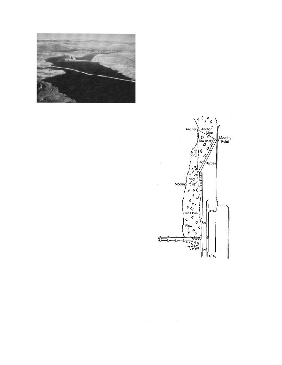
gates or ice spillways tend to work best when lo-
cated as close as possible to the lock entrance.
The Marseilles Lock, on the Illinois Waterway,
located at the end of a canal three miles down-
stream of the Marseilles Dam, presents particu-
larly difficult ice problems. During severe ice
conditions as many as four ice lockages are
required per tow passage. Perham (1988)
described a method using a string of barges to
shear ice away from lock entrances (Fig. 26). A
tow boat would then move the barges into the
open position, allowing traffic to enter or exit
the lock. The method is commonly used at locks
on the upper Mississippi River.*
Figure 25. Chief Joseph shear boom on the Columbia
River at Bridgeport, Washington.
successfully diverts debris and ice from the fore-
bay area (Fig. 25). Located on the Columbia Riv-
er at Bridgeport, Washington, this 3000-ft-long
boom consists of 228 government-surplus moor-
ing floats, 6 ft in diameter by 12 ft long. Each
float contains 2.5 tons of concrete ballast. Perham
(1983) and Appendix B of the Ice Engineering
Manual (U.S. Army Corps of Engineers 1985)
give examples of cross-sectional geometry of
various types of shear booms. The estimated
maximum design load of 103 tons on the 2.5-in.-
diameter main cable on the Chief Joseph boom is
expected to result from wind and wave loading.
Ice diversion at locks
Ice entering locks is a major winter navigation
problem on U.S. waterways. Ice in miter gate
recesses interferes with their operation, and in
severe ice conditions, multiple ice lockages may
be required for the passage of a single tow. Bub-
bler systems and air curtains have been extreme-
ly successful on the Illinois Waterway at Starved
Rock Lock and Dam. The technology of high-
flow air systems is well documented and beyond
the scope of this report (U.S. Army Corps of
Figure 26. Barges used to shear ice away from
Engineers 1985).
a lock entrance. (From Perham 1988.)
In Sweden, four locks connect the upstream
end of the Trollhatte Canal to Lake Vanern,
where an ice escape tunnel connects the highest
lock to the canal below. Vessels descending
ANALYSIS AND CONCLUSIONS
through the system tend to push brash ice from
This review of existing structures summarizes
the lake into the locks. To counter this, the upper
the information gained in the first part of the
lock is allowed to fill with ice, and the ice is then
work unit on structural ice control methods,
flushed out en masse through the tunnel. Blast-
conducted under the River Confluence Ice Pro-
ing is sometimes required, however, to clear ice
blockages at the tunnel entrance (Solve 1986).
Ice diversion near hydropower intakes is simi-
* Personal communication with Edward H. Leuch, U.S.
lar to ice control at locks, in that ice flushing
Army Corps of Engineers, Rock Island District, March 1995.
20


 Previous Page
