Pack ice barriers
Yamaguchi et al. (1981) developed a remov-
able pack ice barrier, constructed of ballasted 22-
in.-diameter steel pipe. The structures, shown in
Figure 23, are 19 ft high and 33 ft long. Placed in
rows, the barriers have protected shorelines and
shoreline structures from damage by 1.3- to 1.6-
ft-thick wind- and wave-driven pack ice in the
Sea of Okhotsk. In rock bed situations, no foun-
dations are needed. Water can flow freely
through the structures' legs, so the effect on ma-
rine life is minimal. Saeki (1992) reported the suc-
cessful performance of the pack ice barrier and
described similar structures. Although this is a
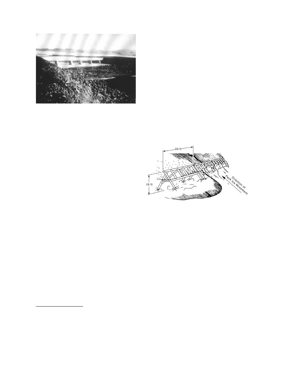
Figure 22. Spillway barrier at the outlet of the Sigalda
marine application, structures of this type could
Reservoir in Iceland.
be adapted to retain breakup ice on major U.S.
rivers. Problems of water level fluctuation and
mained intact. There was sufficient ice down-
foundations in soft sediment or movable-bed riv-
stream of the dam to supply a jam in Cherry-
ers would have to be overcome, however.
field, however. This experience and others show
that an effective breakup ice control structure
needs to be quite close to the site being protect-
ed. Although there have been frequent jams in
Cherryfield since 1968, there have been no inci-
dents of ice jam flooding, suggesting that the
dam continues to have a positive effect.*
A fixed concrete spillway barrier at the outlet
of the Sigalda Reservoir in Iceland was designed
to prevent ice floes from entering the Tungnaa
River and damaging the hydroelectric installa-
tions downstream during low-frequency, high-
discharge events (Fig. 22) (Perham 1983, U.S.
Figure 23. Pack ice barrier, Saroma Lagoon, Sea of
Army Corps of Engineers 1985). No extreme
Okhotsk. Constructed of 22-in.-diameter steel pipe,
runoff events have occurred to test the struc-
the individual units are 19 ft high and 30 ft wide. The
ture's effectiveness since its construction in
direction of ice movement is from lower right to upper
1977.†
left. (After Yamaguchi et al. 1988.)
A timber boom in conjunction with a warm-
water pumping system prevents large ice floes
from passing the spillway at Dickenson Dam on
ICE DIVERSION STRUCTURES
the Heart River in North Dakota. The boom was
installed in 1984 after a large floe damaged the
This final group contains ice control structures
crest gate during breakup. The boom has
whose main purpose is ice diversion. The goal of
performed well, requiring only minor mainten-
this type of ice control is often to prevent ice
ance.** The design is unique in that the main
from entering and blocking hydropower intakes.
cable is guyed out at two points to counter-
To this end, special structures such as shear
weights, to conform to the spillway layout
booms may be used to direct ice past the forebay
(Burgi and Krogstad 1986).
area while diverting the water flow from beneath
the ice. In the absence of hydropower, an ice
diversion structure may guide frazil and floes
away from lock entrances or toward gates capa-
ble of flushing ice past dams. Ice control at
* Personal communication with Mona West, Cherryfield
town office, September 1994.
hydropower intakes is well developed in north-
† Personal communication with Sigmundur Freysteinsson,
ern Europe and Iceland. This report only touches
VST Ltd., Reykjavik, Iceland, May 1994.
on the subject since it is relatively unrelated to
** Personal communication with Duane Krogstad, Bismark
confluence ice situations. However, preventing
Office of Reclamation.
18


 Previous Page
