A
A
Inversion
C
C
B
B
T
A
C
T
B
Horizontal Distance
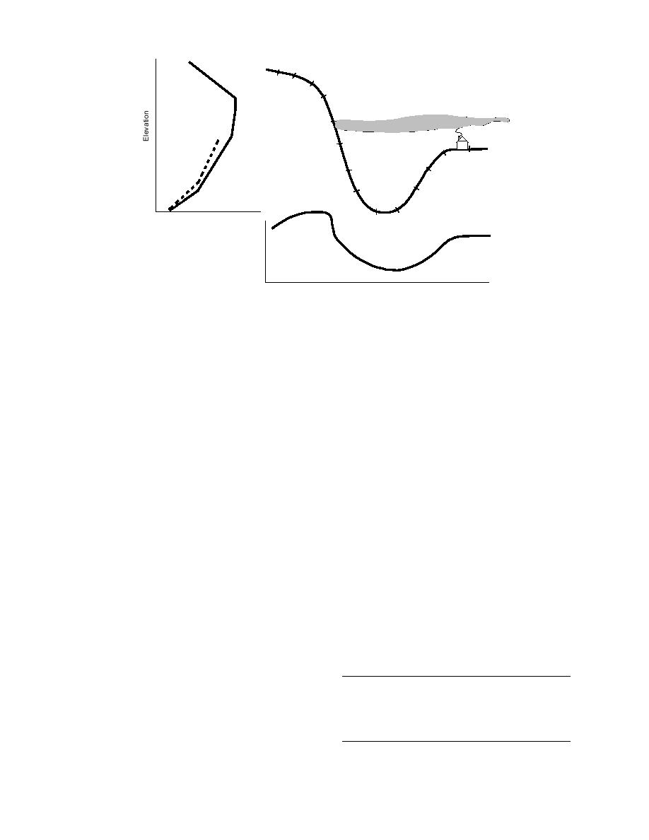
Figure 4. Diagram indicating method of transforming surface temperature observa-
tions to vertical temperature structure.
proximated lapse or inversion structure at the
These are derived from the manufacturer's 10-s
time of observation. This was determined by com-
time constant and a minimum aspiration speed of
paring the temperature at W in Figure 3 about 100
5 m/s to eliminate self heating and the possibility
m above river level, and the temperature at A, 300
of convective heating by the vehicle. This was
m above river level, the apex of observation. A
experimentally tested by comparing the observed
day that has a temperature at A exceeding the
temperature achieved after a 50-m roll at 5 m/s
temperature at W by any amount is an inversion
with the nearby free-air temperature measured
day. A lapse day (not necessarily adiabatic) oc-
by slinging an identical thermistor. The tabula-
curs when the temperature decreases above the
tion indicates that it is possible to examine tem-
elevation of W. Individual layers with lapse or
perature changes on a less than 100-m spatial
inversion structure may be present in either case,
scale on the sparsely traveled rural roads, which
but this analysis stratifies the data with respect to
constitute most of the experimental area, and with
the observed temperature profile and does not
200- to 300-m space resolution elsewhere.
use a temperature in our reference plane as a
A question may arise regarding modification
criterion.
of the temperature field by other passing vehicles.
A shielded, relatively rapid response thermistor
This was not apparent during measurements, but
(YSI 400 with specified 0.63∆T response of 10 s to
an experiment was conducted to estimate the mag-
a step change in air temperature) and its digital
nitude of temperature modification that may be
readout (0.1C) were adapted with convenient
induced. On several still days with surface tem-
perature of less than 20C, the probing vehicle
mountings for a car or truck. The melting point
temperature was verified in the field by wetting
ice on the surface of the thermistor. Some experi-
Table 2. Distance required to respond to a change
mentation was necessary to select mountings 1.25
in temperature.
m above the ground level that were not influ-
enced by radiation or advection of heat from the
Distance (m) to recover 0.95(∆T)
Vehicle speed (m/s)
vehicle; the mirror mount finally selected was
found to reflect the free stream temperature when-
5
60 (minimum aspiration rate)
ever the vehicle was in motion. The response pa-
8
100
rameters are tabulated in Table 2, and define the
16
200
time and space resolution of the temperature mea-
25
310
surements reported in this work.
6


 Previous Page
