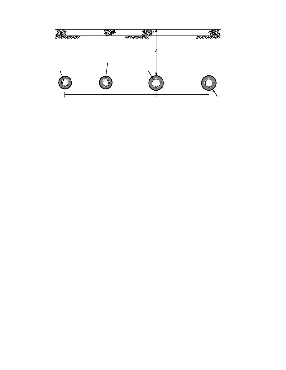
100 mm (4 in.) Concrete Slab
Silty Gravelly Sand
32 mm (1.25 in.)
2.41 m (7.9 ft)
Polyurethane Insulation
~100 mm (4 in.)
~75 mm (3 in.)
PVC Pipes
Steel Pipes
Supply
Return
Return
Supply
HOT
CHILLED
WATER
WATER
54.6 cm
63.5 cm
66.0 cm
2.5 mm (0.1 in.)
(21.5 in.)
(25 in.)
( 26 in.)
FRP Jackets
Figure 9. Construction details for the LTHW site 2.
more than one of the three system types while oth-
Instrumentation, data logging
ers are applicable for only one type of system. Each
and communication systems
The instrumentation consists primarily of type T
of these methods will be briefly described here and
copperconstantan thermocouples constructed
the systems for which each is applicable will be
from 20 AWG thermocouple extension wire. De-
given. More detail on the actual methods used is
tailed information on the location of the 167 thermo-
included in Phetteplace et al. (1991). Worked exam-
couples used on the MTHW sites at Ft. Jackson can
ples of heat transfer calculations for these types of
be found in Phetteplace et al. (1991). A report cur-
systems may be found in Phetteplace and Meyer
rently in preparation will describe in detail the in-
(1990).
strumentation of the Ft. Irwin LTHW sites. Heat flux
sensors were used at all sites, but the results from
Insulation method
these are inconclusive for reasons described
This method is applicable to all system types.
in Phetteplace et al. (1991). On each of the systems
With the observed temperatures on the inside and
instrumented, one site along the length of the sys-
outside of the pipe insulation, the heat flow through
tem was selected. Each of the sites at Ft. Jackson was
the insulation can be easily calculated using the
located at least 7.5 m (25 ft) from the closest manhole
standard formulas for a concentric cylindrical cross
and was chosen as representative of the remainder
section and the thermal conductivity of the insula-
of the system segment between manholes. On the
tion. In using this method on the MTHW systems,
LTHW system at Ft. Irwin, no manholes are used with
we assume that these temperatures are reasonably
all piping junctions buried directly in the ground. The
uniform around the circumference of the insulation.
sites at Ft. Irwin are at least 2.4 m (8 ft.) from the
For the individual conduit system, this assumption
closest junction or change in direction of the pipes.
is supported by the data of Lunardini (1989). Air
Three microprocessor-controlled data loggers
temperature measurements within the concrete
were used in this study. Each of these units was
trench and common conduit systems in this study
equipped with an RS-232 interface and modem so
also support this assumption. For the LTHW sys-
that we could transfer the data from the field sites at
tem at Ft. Irwin, temperatures are measured at four
equally spaced points around the perimeter of the
Ft. Jackson and Ft. Irwin directly to our personal
piping system. These temperatures are then aver-
computer at CRREL for processing. Again, more
aged and subsequently used to find the heat flow.
details on the extent of the data collected at Ft. Jack-
son can be found in Phetteplace et al. (1991), and for
Because of the difficulty of placing thermocouples
between the jacket and insulation of the LTHW
Ft. Irwin will be described in a future report.
system, temperatures are measured on the outside
of the jacket rather than at the outside of the insula-
Data analysis
Several different procedures are used to calculate
tion at these sites. An appropriate thermal resis-
the heat losses from the data collected at the five test
tance for the jacket has been added to the insulation
sites. Some of these procedures are applicable to
thermal resistance in these cases.
15


 Previous Page
