C0
C2
5
To Eagle R.
4
3
2
Gradients
1
(m/m)
0.0165
0.0070
0.0081
0.0143
0.0042
0.0059
0.0044
0.0014
0
50
100
150
200
250
300
350
Distance (m)
E0
F0
F1
5
To Eagle R.
4
3
2
1
0
Gradients
(m/m)
1
0.0099
0.0061 0.0044
0.0027
0.0045
0.0014
2
0
200
400
600
800
Distance (m)
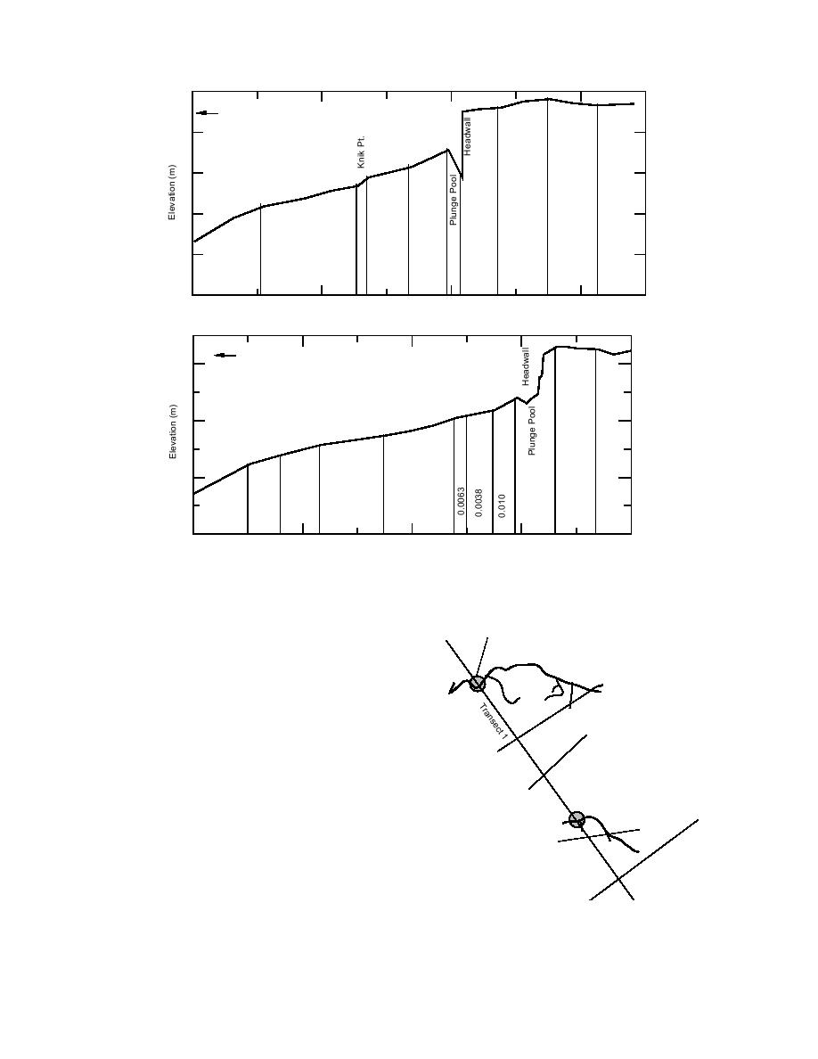
Figure 27. Profiles of elevations along gully thalwegs of two drainages with calculated
gradients indicated (see Fig. 10). TopGully C, bottomGully E.
Channel
wall (Fig. 27). At one or more locations within
Cross-sections
the gully, short segments of the channel have
Bread Truck
sharp increases in gradient. These locations,
which we call knickpoints, may indicate that the
bed profile is not in equilibrium with the exist-
ing hydrological conditions and that the bed
2
ct
se
slope and elevation are actively being modified
an
Tr
by scour during flood or ebb. Such a progressive
t3
c
se
deepening of the gully thalweg and reduction in
an
Tr
the channel gradient may be in response to the
on-going headwall erosion and extension of
each gully into the mudflats.
Parachute
Channels above each headwall are lined by
vegetation and their bed slopes range from 0.001
Transect 4
5
to 0.004 m/m, generally being less than the gra-
ct
se
n
dients within the gully proper. With distance,
a
Tr
slopes gradually reverse in direction and dip up-
stream across the unvegetated mudflats next to
Figure 28. Places where gully cross sections and peak
the ponds.
flow were estimated (intersection of gully and tran-
Both the relatively rapid erosion and exten-
sect 1). Figure 4 shows their location within the study
sion of the gully system and their relatively
area.
29


 Previous Page
