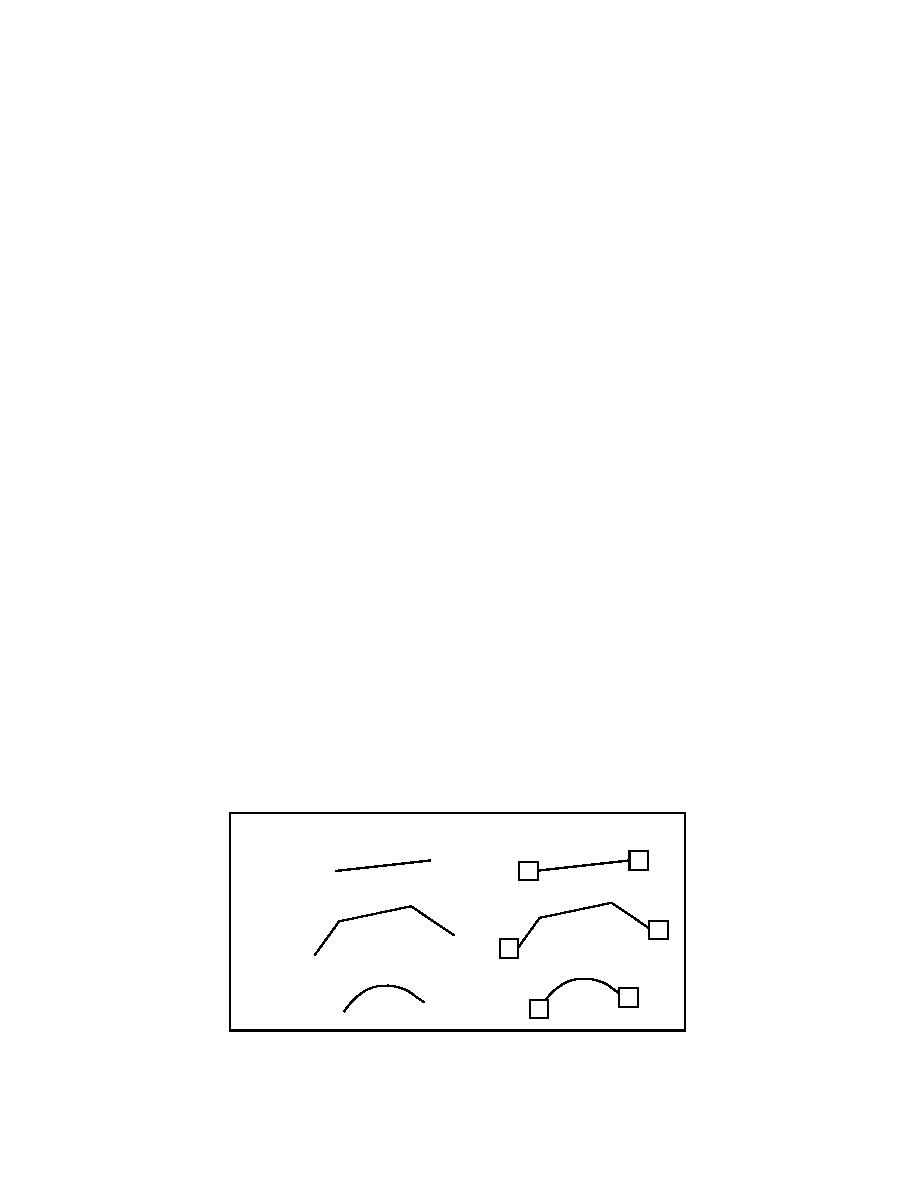
used in AutoCAD to digitize linear features is the
cates an edge is not necessary, because of the nature of
polyline. An AutoCAD polyline is a multivertex,
the coverage model and the CLEAN process.
multisegment, and two-dimensional entity. Three-
Annotation features
dimensional polylines can be created in AutoCAD, but
those with vertices at varying Z coordinates should be
Text objects are used to indicate additional attributes,
avoided, as the conversion process will ignore them. If
such as pipe conditions or installation dates, or simple
the polyline is at a consistent elevation, it can be cap-
labels on objects, such as a river name. This text, how-
tured for future use, as we will see. As noted, the light-
ever, has no connection to the object, rather it simply
weight polyline, which is a simple, noncurved, 2-D
provides a visual aid on the drawing canvas. The text
version of a polyline, may be used. While AutoCAD
object represents data that can be captured from the
users often prefer these entities because of their low
drawing as ARC/INFO annotation. Each piece of text
overhead, it does not matter for the conversion process,
can be captured, along with its size, value, and rotation
and they are treated as a regular polyline. Any further
angle, as annotation or as a point feature located at the
reference to an AutoCAD polyline will imply a polyline
insertion point of the text. No information concerning
or lightweight polyline object. Note that ARC/INFO
the font or AutoCAD text style is needed. While it is
will create nodes at the end points of the line, polyline,
useful for the data provider to deliver necessary text
or arc entities when they are converted to ARC/INFO
fonts to the ARC/INFO user, it is not crucial to the con-
arc features. Figure 5 illustrates ARC/INFO arc fea-
version process because ARC/INFO uses its own set of
tures and corresponding AutoCAD entities.
text symbols.
Attributes, as noted in the section on point features
Polygon features
above, are textual objects that are part of a compound
As noted previously, an ARC/INFO polygon feature
block insert. This text, in addition to being captured as
is created from arc features via the CLEAN command.
point data and linked back to the symbol, can be cap-
This being said, information that is intended for con-
tured as annotation and treated as such in the GIS data-
version into ARC/INFO arc features, then CLEANed
base. These data will follow the same rules and proce-
into polygon features, should be carefully digitized to
dures as text.
avoid error. Polylines could be digitized either as closed
(an option when creating the polyline), or open, with
AUTOCAD SYMBOLOGY AND DATA
the start and end points identical. If these methods are
ORGANIZATION
used, closed and snapped polylines will be easily con-
verted into ARC/INFO polygon features. Digitizing
AutoCAD organizes its data, stored in file-based
polygons that overlap will result in the creation of mul-
drawings, into a series of overlays called layers. In
tiple polygons, as this is not allowed in the polygon
addition to layers, the user can utilize methods of sym-
model. This may also lead to undesirable results. If the
bolization such as block symbols, color, line type, and
line work is digitized and snapped correctly, CLEAN
line width to visually describe the drawing entities.
Attribute information can be carried along in the form
This means that a closed or open polyline that dupli-
of AutoCAD block attributes as well.
AutoCAD Entity
ARC/INFO Arc/Node Feature
2
Line
1
Polyline
2
1
Arc
2
1
Figure 5. Representing ARC/INFO arc features with AutoCAD
entities.
6


 Previous Page
