PAT
AREA
PERIMETER
GRID#
GRIDID
12.25
5.75
1
1
11.75
4.75
2
2
1
1
2
1
4
2
PAL (Internal File)
3
Poly# Poly-ID Arc Numbers Node Numbers Other Polys
4
3
1
1
1,2,3,4
1,2,3,4
2
2
2
3,5,6,7
3,4,5,6
1
2
5
6
AAT
FNODE# TNODE# LPOLY# RPOLY# LENGTH
PIPE#
PIPE-ID
3
4
3
3
1
2
10.25
NAT
RECORD
ARC#
PIPE#
PIPE-ID
3
3
1
0
4
3
2
0
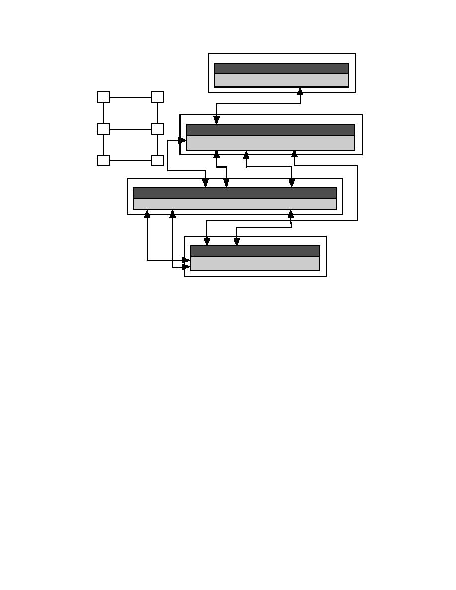
Figure 4. ARC/INFO polygon features.
Arc features
ing that can have several shapes. The AutoCAD shape
AutoCAD line objects are simple two-point objects
entity has its definition stored in a shape font definition
that delineate an edge of a 2-D or 3-D entity. These
file. Either of these can be converted into point fea-
objects translate directly into ARC/INFO arc features.
tures. The AutoCAD block entity can be used to cap-
The problem from a GIS perspective is that any break
ture a multitude of data types. A block is a compound
in the line results in a break in the connectivity of the
object, defined from a set of other AutoCAD entities.
feature. Lines that are broken in two, for example, to
For example, a fire hydrant symbol could be created
place a piece of text, can result in difficulty in GIS model
from a set of lines, arcs, and polylines, drawn in vari-
creation. Several line entities can be strung together to
ous colors and on various layers, to look like a fire
form linear boundaries, but they should be snapped so
hydrant. The block is then defined and saved as a tem-
the end points coincide. A more appropriate AutoCAD
plate. This block can be placed multiple times in the
object to use would be the polyline or LWpolyline (light-
drawing. Each individual instance of the block is called
weight polyline) object. These are multivertex linear
an insert. Each block insert can be captured as a point,
objects that can be used to symbolize a road centerline,
based on the location where it was inserted into the
river edge, or any other 2-D object. LWpolylines are
drawing. There are options to create ARC/INFO arc
often used when there is no need for 3-D elevations on
features from the individual geometric parts of the
the vertices, since they take up much less storage in the
block, but these must be valid object types. In addition
AutoCAD database. Each segment of a polyline can
to the symbol, a block can contain a set of attributes,
contain a bulge factor, making its segment a geometric
which are items of descriptive text that can accompany
arc. Again, these entities should be continuous if they
the symbol. The block definition contains a set of
are being prepared as layers to be converted into ARC/
attribute definitions called tags, and each instance of
INFO coverage arc features.
the block (insert) contains the tag attributes. Our hypo-
AutoCAD geometric arcs and circles can be con-
thetical hydrant block could have two attributes asso-
verted to ARC/INFO arc features and will be tessel-
ciated with it: the hydrant ID number and the date of
lated into segments approximating the curved segment,
installation. These can be captured as text annotation,
with one segment per degree of arc. The primary entity
but they can also be stored as a point feature.
5


 Previous Page
