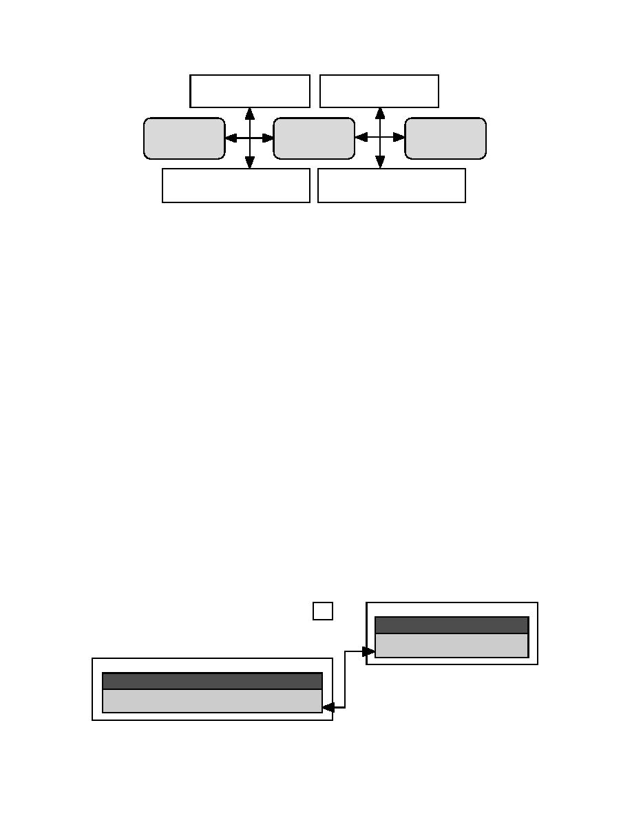
CAD Software
GIS Software
Graphic
Coordinate
Attribute
Database
Database
Database
AutoCAD Drawing
ARC/INFO Coverage
Figure 1. CAD and GIS software data storage.
in a LAB file that is linked internally to the point
1-D, and 2-D features of points, arcs, and polygons.
attribute table (PAT).
These will then map through the conversion from
AutoCAD points, block inserts, lines, polylines, light-
Arc features
weight polylines, circles, arcs, and other drawing enti-
Arcs represent both linear features and the borders
ties. Each ARC/INFO feature is connected to its fea-
of polygon features. Linear features represented by arcs
ture attribute table via an internal ID system. This is
can have length but no area, such as a contour line, or
not a major concern to the AutoCAD user. However,
can be long narrow features whose width is not appar-
creating a way to uniquely identify each entity by a
ent at a given map scale, such as a river. Each linear
system-dependent identifier might be a concern. For
feature may be made up of many arcs. Since arcs also
example, each fire hydrant in a drawing may have some
form the basic linear infrastructure from which com-
unique number assigned by the Public Works Depart-
plex GIS processes are derived, such as tracing and
ment. This ID might be placed in the drawing to iden-
surface computation, it is very important that an entity
tify the hydrant. A CAD user might be satisfied to place
be continuous. An arc is a continuous string of X,Y
this on the drawing to be plotted out. The GIS would
coordinate pairs (vertices), beginning at one location
need to store this value with the hydrant in the feature
and ending at another, stored in an ARC file. Geometri-
attribute table, so it can join it to other databases in the
cally, an arc is similar to an AutoCAD Polyline entity,
future. As we will see, there are various methods to
which is often used to create ARC/INFO arc features.
capture this type of information into ARC/INFO.
The topological structure is created so that the starting
Point features
and ending points are special locations known as nodes.
The in-between points are the vertices that define the
Points represent geographic features that have no
area or length, such as sewer manholes, bank locations,
arc's shape. This structure is used to trace linear sys-
tems and to form the boundary of polygon features. This
accident locations, or features that are too small at a
means that there should be no break in the continuity
given scale to be represented by their dimensions. Points
of entities drawn in AutoCAD to represent features in
are stored as single X,Y coordinate pairs. In a GIS,
ARC/INFO. If a text entity is used to indicate the
descriptive data are stored in a database, then related to
diameter of a water line, it should not break the conti-
the spatial database that holds the coordinates. As shown
nuity of the water line and should be placed above or
in Figure 2, the spatial database stores the coordinates
LAB (Internal File)
1
WELL#
X-COORD
Y-COORD
1
150.75
209.45
2
254.12
400.23
PAT
AREA
PERIMETER
WELL#
WELL-ID
0.00
0.00
1
1
0.00
0.00
2
2
Figure 2. ARC/INFO point feature.
3


 Previous Page
