below the line. The AutoCAD user must, in this situa-
ARC/INFO CLEAN command can be used to repair
tion, remember that the final destination of these
overlapping and unconnected areas, but it is preferable
mapped data is not a paper plan, used for visual pur-
to have the data created appropriately at the time they
poses, but a digital model to be used for analysis. Other
are digitized. Polygon features will not be directly cre-
tools in ARC/INFO can be used to manipulate the lo-
ated at the conversion level but will be assembled from
cation of descriptive text. The arc attribute table (AAT)
the geometry that defines the arc features after using
and node attribute table (NAT) are used to store the
CLEAN.
attributes (Figure 3).
Annotation features
Polygon features
Annotation features are used to store descriptive text
Polygons are used to represent area features, such
that may or may not be connected to spatial features,
as states, counties, lakes, and land-use zones. Polygons
such as points, arcs, and polygons, in the coverage.
enclose areas that meet a user-specified set of common
Annotation may be derived from the database values
characteristics for the phenomena being represented.
of a point, line, or polygon feature, or it can be
In the ARC/INFO model, a series of arc features is used
standalone. Annotation can be captured from AutoCAD
to create a closed area that defines the polygon feature.
and stored in the coverage for later use, mostly for cre-
A polygonarc list (PAL) file defines the relationship.
ation of cartographic map output.
Figure 4 illustrates this relationship graphically. The
attributes are stored in the polygon attribute table (PAT).
MODELING ARC/INFO FEATURES WITH
An additional characteristic of a polygon feature is that
AUTOCAD ENTITIES
it has a special point that lies within its border called
the label point. A label point is used by ARC/INFO to
This section focuses on how to represent informa-
identify the polygon, because the polygon is actually
tion in an AutoCAD drawing with AutoCAD entities,
not the arcs that make up its boundary but a set of rela-
with the purpose of converting them into ARC/INFO
tionships between those arcs. Any AutoCAD entity that
features.
can be used to represent a point feature can be used to
Point features
model the label point of a polygon. Polygons can also
model holes or voids in a region. When creating data to
Discrete coordinate locations can be represented in
be converted into ARC/INFO polygons, CAD users
the drawing in a number of ways, all of which can be
should snap end points of lines together and not create
converted into ARC/INFO point features. The
regions where the areas of polygons would overlap. The
AutoCAD point entity is a location defined in the draw-
ARC (Internal File)
PIPE#
1
<coordinate series>
2
<coordinate series>
1
2
AAT
FNODE# TNODE# LPOLY# RPOLY# LENGTH
PIPE#
PIPE-ID
1
2
1
1
0
0
10.25
NAT
RECORD
ARC#
PIPE#
PIPE-ID
1
1
1
0
2
1
2
0
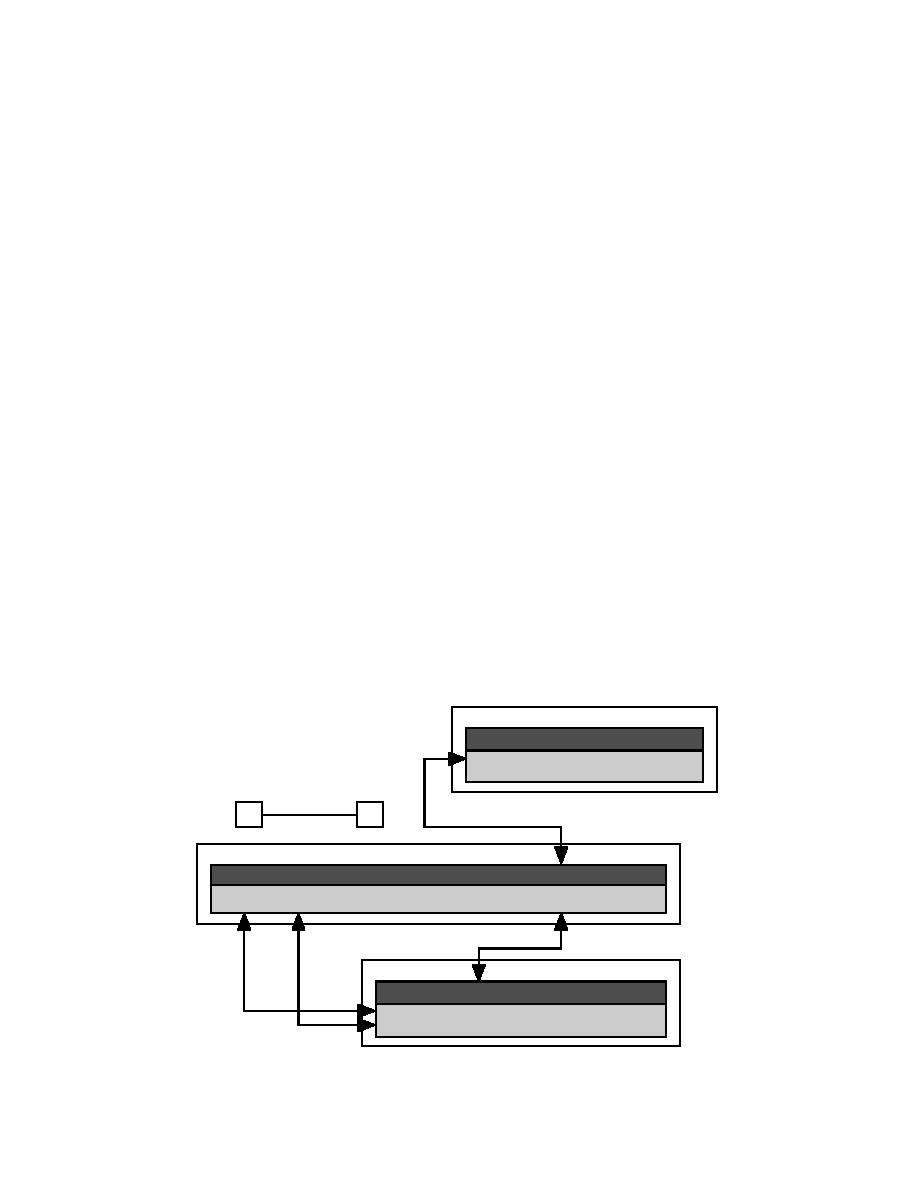
Figure 3. ARC/INFO arc/node features.
4


 Previous Page
