m
in.
70
60
1.5
Wheel Load, W
89.0 kN (20,000 lb)
50
66.7 kN (15,000 lb)
44.5 kN (10,000 lb)
40
22.2 kN ( 5,000 lb)
1.0
30
20
0.5
P = 2W
10
0
0
10
50
100
500
kPa
1
5
10
50
100 psi
cNc
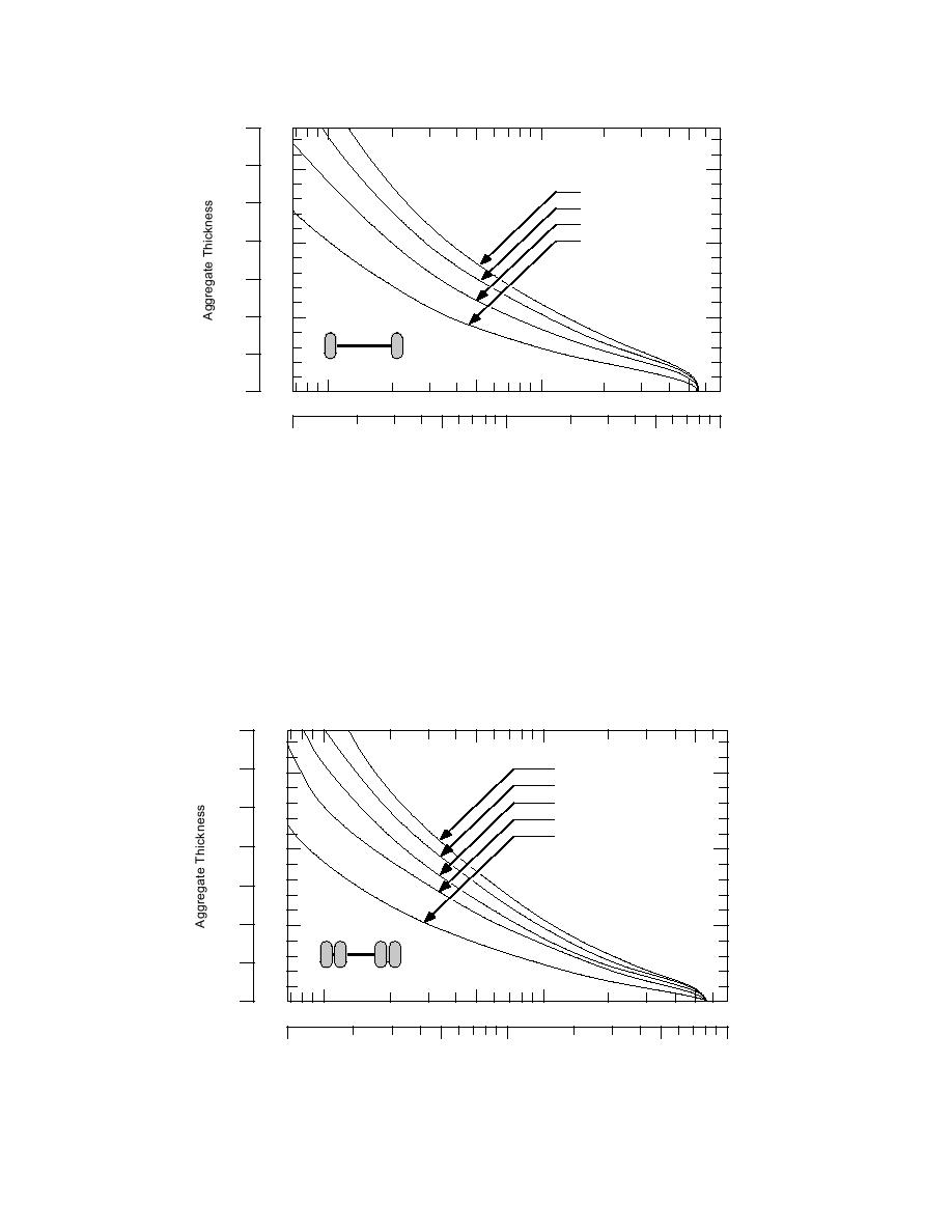
Figure 1. Aggregate thickness design curve for single-wheel load on gravel-surface roads.
(From TM 5-818-8.)
aggregate that meets base course requirements is
evidence for the requirement of high-quality ag-
presumably required. Field Manual FM5-430-001
gregate is the fact that the design technique is
(1994) recommends that base course material have
based on experiments that used crushed-rock ag-
minimum CBR values of 80 to 100. Soils that yield
gregate (Barenberg et al. 1975).
these values include crushed rock, mechanically
Guidance for selecting wheel loads and contact
stabilized aggregates, and well-graded gravel (e.g.,
pressures to use with this design is not given in
FM5-430-001; Holtz and Kovacs 1981). Further
TM5-818-8; thus, it is now provided. For single and
m
in.
70
Wheel Load, W
60
89.0 kN (20,000 lb)
1.5
71.2 kN (16,000 lb)
53.4 kN (12,000 lb)
50
40.0 kN ( 9,000 lb)
17.8 kN ( 4,000 lb)
40
1.0
30
20
0.5
P = 2W
10
0
0
10
50
100
500
kPa
1
5
10
50
100 psi
cNc
Figure 2. Aggregate thickness design curve for dual-wheel load on gravel-surface roads. (From
TM 5-818-8.)
2


 Previous Page
