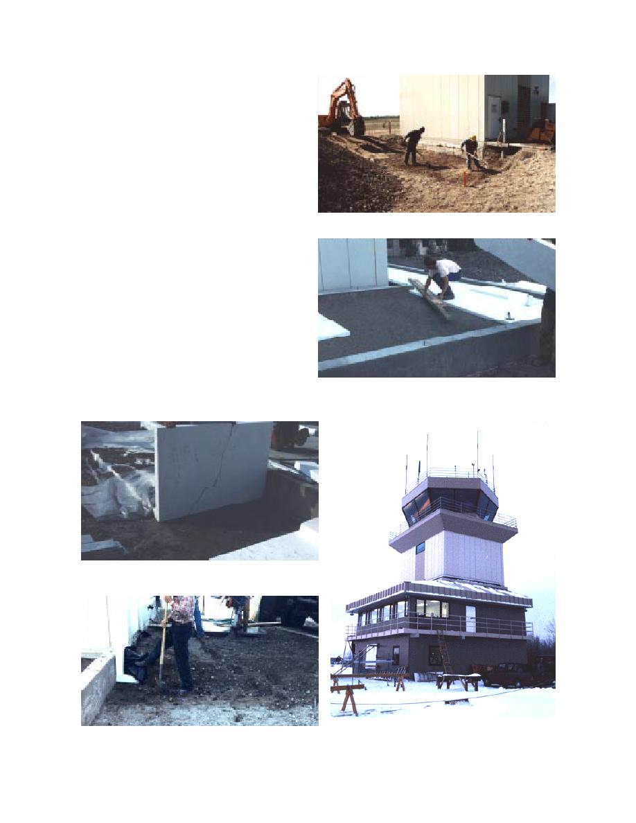
on the outside of the wall is standing on top of the
footing.) The laborer inside the foundation is
placing the floor insulation. Note that the surface
was prepared so the insulation lies flat and thus is
less vulnerable to breakage. A plastic 8-mil film
was placed over the insulation prior to the floor
being poured. Figures 8 and 9 show the installa-
tion of the ground insulation. In Figure 8 the
ground insulation is being placed horizontally on
top of the footing and the plastic film placed over
it. The wire that the laborer is holding is a temper-
ature sensor that will be installed below the insul-
Figure 6. Excavation of foundation.
ation. Figure 9 shows the stem wall insulation in
place and backfill placed over the ground insula-
tion. Figure 10 is the existing control tower and
the complete addition.
RESULTS AND DISCUSSION
Temperatures were recorded for the winters of
199091, 199192, and 199293. During the early
part of the first winter the addition was still
under construction; it was only occasionally
heated until the addition was completed and
occupied in December. The second winter there
Figure 7. Floor insulation.
were numerous personnel changes at the weather
station and thus thermocouple readings were
Figure 8. Ground insulation, temperature sensor.
Figure 10. Existing control tower and complete addi-
Figure 9. Ground and stem wall insulation.
tion.
6


 Previous Page
