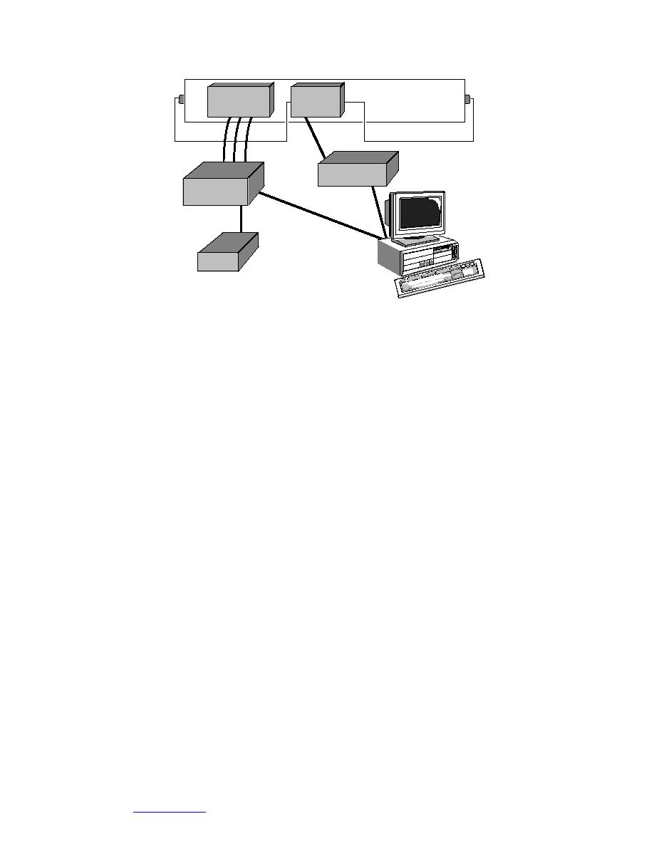
Experimental
Thermocouple
Pipe Heater
Apparatus
Terminals
Control
Watt-Meter
Multiplexor
Box
Ice Point
Figure 20. Data acquisition system for use with the 1-ft 1-ft enclosure.
and y coordinates; these were placed 66 in. from the coolant supply end, except
where noted. The total interior length was 106 in.
Procedure
Once the apparatus was connected to a coolant supply and electrical power
source, several adjustments were possible. The coolant temperature could be
adjusted, the coolant flow through each panel could be controlled, and the energy
input to the pipe heater(s) could also be adjusted. Experiments consisted of obtain-
ing a range of temperature conditions for both the interior walls of the apparatus
and pipe(s) at steady-state conditions. Steady state was determined to be obtained
once the temperatures along the top of the enclosure were changing by a small
amount and in an apparently random fashion. Once a steady-state condition was
reached, three sets of data from all of the thermocouples and the watt-meter were
stored on an approximately hourly basis. Thus for each condition, three sets of data
were collected. Temperature data from the 2-ft 4-ft enclosure were collected con-
tinually on an hourly basis.
RESULTS
General information
Data obtained from the experimental and numerical experiments are summa-
rized in Appendixes A and B, respectively. Physical data are based on the average
of three hourly readings. Temperatures, Nusselt number, Rayleigh number, heat
flow though the interior wall, and the average thermal conductance at the interior
enclosure surface are presented. Heat flow through each side, assuming 1 ft of
enclosure length, was calculated by using the temperatures around the insulation
and averaging the heat flows calculated at each thermocouple location (physical
experiments) or the temperatures at each node location (numerical). These values
30
Go to Contents


 Previous Page
