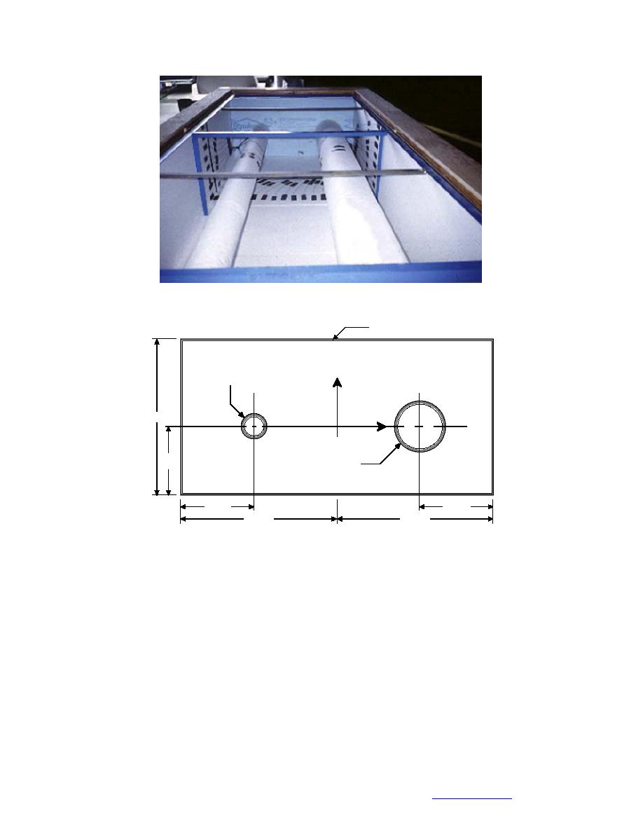
Figure 18. 2-ft 4-ft enclosure with 4-in. and 8-in. insulated pipes.
0.5 in. EPS Insulation
4-in. diameter
y
24.5 in.
x
10.75
8-in. diameter
in.
11.5 in.
11.5 in.
24.5 in.
24.5 in.
Figure 19. Schematic diagram of the 2-ft 4-ft enclosure.
with Industrial Computer Source data acquisition boards. These boards (a total of
four) were mounted in a separate enclosure and were accessed using an 8-channel
multiplexor board mounted in one of the PC slots. Figure 20 is a schematic dia-
gram of the data acquisition system; note that an electronic ice point bath was in-
cluded in the thermocouple circuit for temperature compensation. The ice point
bath was added because, during calibration of the system, it was found that the
onboard electronic temperature compensators were not accurate. A data acquisi-
tion and display program was written to display and store the thermocouple data
and measurements of the energy input to the pipe heater(s). These data were stored
in ASCII format on floppy disks for later analysis. Thermocouple locations for the
1-ft 1-ft enclosure are in Table 6.
The data acquisition system for the 2-ft 4-ft apparatus was based on a Campbell
Scientific CR-10 system with four multiplexor expansion boards. One hundred and
twenty-two thermocouples were installed. Table 7 contains the thermocouples' x
27
Back to Contents


 Previous Page
