0.8
0.6
0.4
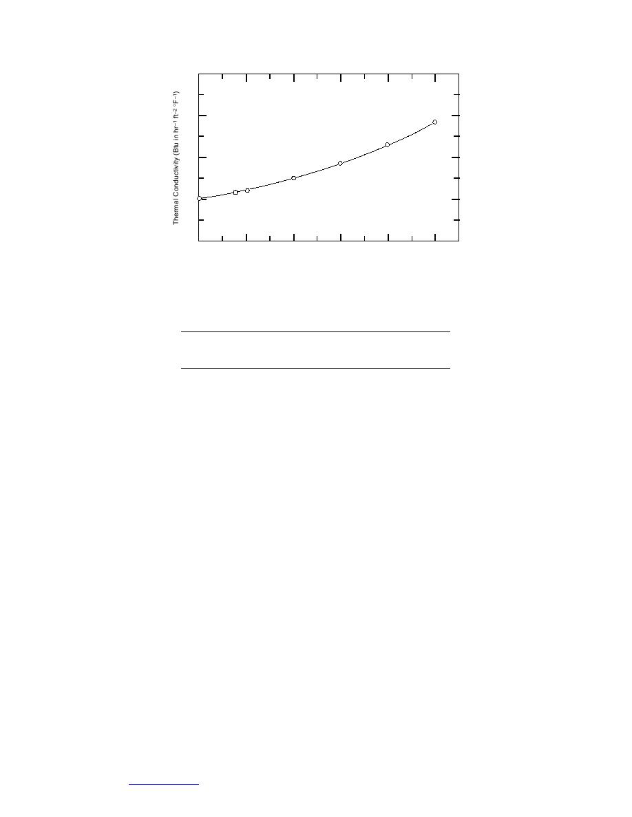
K = 0.196851 e0.0021168(T)
0.2
0.0
0
100
200
300
400
500
Mean Temperature (F)
Figure 17. Thermal conductivity of fiberglass pipe insulation.
Table 5. Test apparatus configurations.
Enclosure size
Nominal pipe diam.
Pipe treatment
1 ft 1 ft
4 in.
uninsulated, painted* , insulated
2
uninsulated, insulated
2 ft 4 ft
8, 4
insulated
* The uninsulated pipe was painted with a low-emissivity paint (Rust-
Oleum Aluminum No. 7715).
sure. Unfortunately, CRREL had at this time recently done away with its extreme
low temperature capability for environmental reasons.
Several years after these initial experiments, CRREL regained its extreme low
temperature brine capability and the apparatus was moved and replumbed to take
advantage of a coolant as low as 70F. Prior to resuming experiments, the inte-
rior surface-mounted thermocouples were replaced with 30-gage surface-mount
thermocouples in order to measure the surface temperatures more accurately.
Once experiments were resumed, further experiments were conducted using
the uninsulated 4-in. pipe. When these were completed, experiments continued
with various pipe treatments and configurations. Figure 17 is a plot of the thermal
conductivity of the fiberglass pipe insulation used. Table 5 summarizes the test
apparatus configurations.
The second apparatus was constructed similarly; however, no plywood sepa-
rated the cooling panels from the insulation, and a metal interior frame was used
to help support the cooling panels. Figure 18 shows the 2-ft 4-ft apparatus prior
to installing the lid. Figure 19 shows a cross section with dimensions and pipe
locations.
Data acquisition system
Two different data acquisition systems were used, one for the 1-ft 1-ft enclo-
sure and another for the 2-ft 4-ft enclosure; type-T thermocouples were used to
measure temperature, and a power meter was used to measure the power sup-
plied to the pipes.
For the 1-ft 1-ft enclosure, a personal-computer- (PC-) based data acquisition
system was assembled using an 80286 processor-based computer in conjunction
26
Go to Contents


 Previous Page
