during testing. Operational usage of the system
Auger drive motor
The stiff tines and cutter of the cutter/grate sys-
indicated that extended run-time was possible
tem added to the torsional resistance of the auger.
with the grates installed. However, some plug-
A new hydraulic augerhead motor with twice the
ging of the grates was experienced. For the most
torque and half the speed of the original was
part, the debris was confined to the upper and
installed. In the process, the hydraulic hoses were
lower 5 cm of the grates. The material lodging in
replaced, as they had been abrasively worn. Dur-
the grates consisted of small chunks of wood
ing dredging operations, the protruding drive
(boardwalk), hard vegetative nodules, and root
motor is forced through the undredged material
masses. Some modification of the grates was
to the side of the dredgehead. This causes wear on
done to reduce entrapment, but the cause of the
the component as well as resistance to forward
plugging was the deflection of the grates by
motion. The drive motor needed to be located
material slightly larger than the grate openings.
behind the shroud, and the auger driven with a
During the interval between the July and Sep-
chain.
tember deployments in 1995, an improved sys-
With these changes made to the system, actual
tem was designed and fabricated. The grates
production dredging commenced in mid-Septem-
were stiffened by using thicker stock for fabrica-
tion, 9.5 mm rather than 4.75 mm. The grates
ber of 1995. Progress was slow but consistent, with
the processing of vegetation continuing to be
were machined in a T shape to allow slightly
problematic. Difficulties with the winch traverse
oversized debris to pass through without jam-
system persisted, but solutions were formulated
ming. An improved transition box behind the
and these difficulties were circumvented on a tem-
intake allows backflushing and manual cleaning
porary basis. A series of unrelated events closed
of the rear of the grates. Finally, the grates were
down operations at the Flats, and on 24 Septem-
designed to fit flush with the front of the auger
ber, dredge operations were halted for the season.
head shroud (Fig. 8).
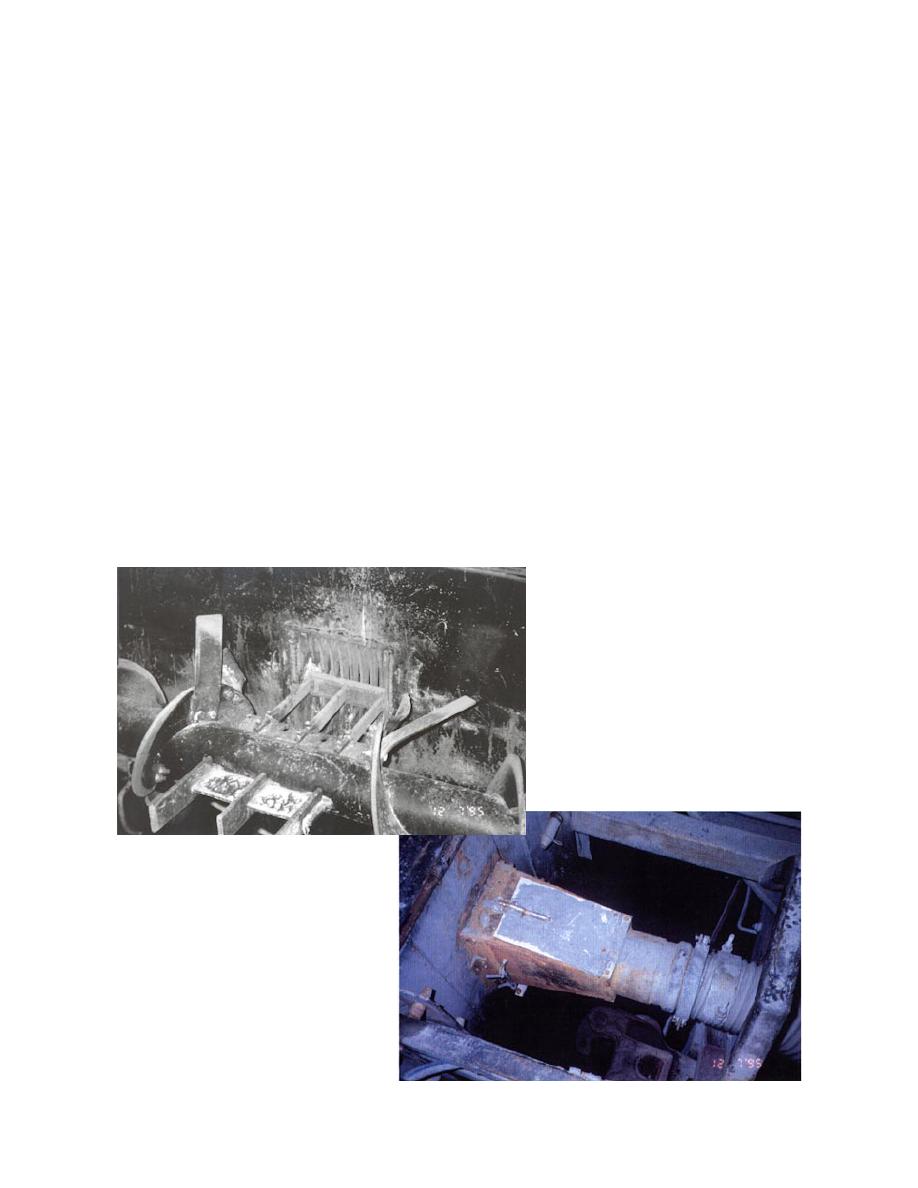
a. Cutter and grates. Note vertical stiff tine.
b. Top view of transition box showing manual
cleanout.
Figure 8. Mk. II cutter/grate system.
7


 Previous Page
