determine the optimal method of achieving mini-
start from scratch and troubleshoot every suspect
mal percolation rates into the pad. With a 15-cm
component in the system. The following is a list
layer of compacted peaty silt lining the basin, per-
of problems uncovered and actions carried out to
colation rates were low enough (<105 cm/s) to
resolve them.
be acceptable for use. The basin was instru-
mented to monitor water level, sediment and air
Flexible hose sections
temperature, and sediment moisture, parameters
Due to poor construction, end connectors on
critical to the remediation process for WP.
the 25-cm-diam. hose sections failed on a regular
basis. All the flexible hose sections in the spoils
line were removed and replaced with short sec-
INITIAL DEPLOYMENTS
tions of rigid PVC pipe. After one section of PVC
Initial deployment of the dredge took place in
pipe blew an end fitting, the number of screws
October of 1994 (Walsh et al. 1996). Due to the
holding the fittings to the pipe ends was doubled
lateness of the season and delays caused by im-
from two to four. No further problems were
properly running equipment, very little dredging
encountered.
was accomplished. Enough spoils were pumped
for only two composite samples, one of which
Sensors
was heavily contaminated. However, results
Closer examination of the dredge function
demonstrated that an operable dredge system
feedback sensors (intake suction, pump output
will effectively remove contaminants from the
pressure, system hydraulic oil pressure, and cen-
environment.
trifugal pump hydraulic oil pressure) indicated
Early in the 1995 dredging season, a number of
that the output signal range was from 1 to 6 VDC,
improvements were made to the equipment, but
not the 05 VDC specified in the contract. This re-
problems continued to plague the operation. Ini-
sulted in miscalibration and the clipping of the
tial dredging operations were quite discouraging,
higher signal output (56 VDC). In addition, the
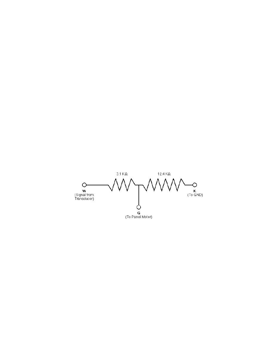
Figure 5. Sensor voltage divider (typ. each sensor).
showing little improvement over the previous
sensors were wired to the wrong inputs on the
season. Output from the various dredge sensors
video panel meter that transforms the sensor sig-
was still unusable, reading below known maxi-
nals into output data for transmission over the
mum system values at full operating conditions,
video system. These were rewired to the correct
and the pump was not operating correctly. Top
inputs. A voltage reduction circuit using preci-
speed was attained at about 50% of hydraulic
sion resistors was designed at CRREL and in-
throttle, and spoils flows could not be main-
stalled between the sensor output leads and the
tained. In addition, the 25-cm-diam. flexible sec-
video panel meter (Fig. 5). This circuit attenuates
tions in the spoils line continued to blow fittings.
the signal 20%, resulting in an input signal of 0.8
Consultations with the equipment manufacturer
to 4.8 VDC to the panel meter. Voltages now cor-
did not result in a solution, and discussions with
responded to the range of the panel meter, 05
the pump manufacturer and an engineer at the
VDC. The panel meter was reprogrammed and
Waterways Engineering Station in Vicksburg
pumping tests rerun to obtain data for pump
indicated that a second look at the pump was
evaluation.
warranted.
After two unsuccessful attempts at using the
Pump
system as configured, the decision was made to
With the sensors wired correctly and recali-
4


 Previous Page
