tivity of the soil. The factor of 2 accounts for the
highly conductive settings where radar techniques
round trip propagation of the pulse, to and from
fail. The unit consists of a backpack-mounted
the reflecting surface.
transmitter and coaxial coil antennas. The closely
The dielectric permittivity of soils within the
spaced antennas (vertical magnetic dipoles) are
PRDA was determined from the timedistance
mounted on wheels and towed by the operator.
slope of hyperbolic diffraction asymptotes.
In operation the primary magnetic field induces
Several permittivity determinations were made
secondary currents in nearby metal objects, which
in March 1994 when the soils were frozen. Addi-
in turn induce a secondary magnetic field that is
tional permittivity determinations were made in
sensed at the receiver. After pulsing the transmit-
June 1995 when frost was absent and a layer of
ter (the repetition rate is 75 Hz), the response
from the ground generally decays in about 200 s.
silty backfill covered the site. The mean frozen
soil permittivity was 4.4. Five determinations of ε
The responses from metal may persist for 400500
s. These longer duration responses are detected
in June 1995 gave a range of 5.4 to 7.4, with a
mean of 6.8. All of these values are reasonable for
in time and measured in millivolts (mV) of in-
both frozen and unfrozen silty sand and gravel of
duced coupling. This high-sensitivity receiver can
low moisture content (Arcone and Delaney 1985).
detect a drum-sized metal object at a depth of
With use of the mean ε of 6.8, the time range
over 3 m beneath the antenna. Digital data for up
settings for 100- and 400-MHz transducers pro-
to 10,000 stations are recorded on a hand-held
vided an approximate depth range of 20.0 and 5.2
datalogger.
m, respectively, in these materials. The in-situ sig-
EMI data recordings were controlled by the
nal wavelengths are about 30 cm at 400 MHz and
carriage survey wheel, resulting in approximately
1.2 m at 100 MHz. Accurate depth calibration of
four readings per meter. Each data point was sub-
the radar records is difficult, however, owing to
sequently assigned an X,Y location and the data
the local variability within these glacial deposits.
were contoured for comparison with the radar
profiles. The amplitude of the secondary field re-
sponse can vary with the size, depth, and lateral
Electromagnetic Induction
proximity of the buried metal. The off-line re-
(EMI) Technique
To complement the radar data and remove some
sponses can complicate interpretation and careful
of the ambiguity in interpretation, we used an
survey techniques are required. Readings between
EM61 electromagnetic unit manufactured by
100 and 1000 mV were considered moderate to
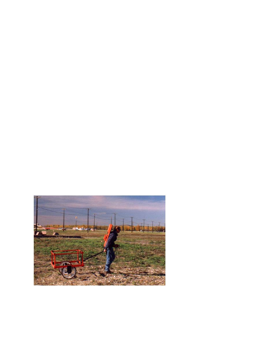
Geonics LTD, Mississauga, Ontario (Fig. 4). It is a
strong anomalies, while readings greater that 1000
time-domain metal detector that can operate in
mV were considered very strong anomalies. Read-
ings from nearby locations with-
out disturbance gave background
noise levels of approximately 10
mV. For these investigations,
readings greater than 100 mV are
considered potential targets, but
any persistent deviation from
background levels must be con-
sidered to signify the presence of
metal.
MEASUREMENTS
The entire PRDA was surveyed
using both GPR and EMI tech-
niques in the late winter of 1994,
when the site was covered by 30
to 50 cm of snow. The GPR trans-
Figure 4. Geonics EM61 electromagnetic induction unit during a survey.
ducers were towed behind a
The operator tows the antenna, while the backpack unit generates signals.
tracked vehicle and the EMI an-
Data are recorded on the hand-held datalogger.
tenna was towed by hand along
4


 Previous Page
