gressive time steps and converted to audio fre-
the direct transducer coupling). This technique
quency scans for display and storage at a rate of
allows enhancement of the lower amplitude later
32 per second. The scans were stacked to improve
signals that reflect at layer interfaces and material
signal quality and to reduce the amount of stored
transitions. The technique is well known and is
information. Each recorded scan can be displayed
used extensively for shallow subsurface explora-
using an operator selected time-range to suppress
tion (Morey 1974).
the higher amplitude early returns (especially from
The radar antennas discussed in this report
were 100- and 400-MHz shielded dipole pairs,
which radiate pulses with 20- and 5-ns duration
respectively. The antenna terminals connect di-
rectly to the transmitter and receiver electronics
and an entire unit is called a transducer. When
using the 400-MHz transducer, the signals were
recorded for a time range of 100 ns. To search for
deeper horizons, profiles were recorded with the
100-MHz transducer at a time range of 400 ns.
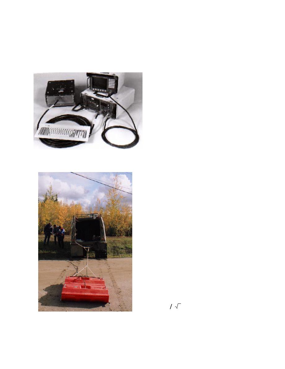
The transducers were towed along the ground
surface by hand or tracked vehicle (Fig. 3). Sur-
vey speed was approximately 1 m/s. This speed
provided a profile data density of about 16 scans
for each meter of transducer travel. The bottom
of the transducer was maintained in close contact
with the ground or snow surface to maximize
signal transmission through the air/ground in-
Figure 2. GSSI ground-penetrating radar system, video
terface. The profile data were later filtered to re-
display, 400-MHz transducer and cables.
move noise and horizontally scaled between event
markers to compensate for uneven towing speed.
GPR events within a profile consist of bands of
reflections from continuous horizons and discrete
hyperbolic diffractions that originate from indi-
vidual targets and abrupt material transitions. The
depth to a target is calculated from the apex of
each hyperbola when the material dielectric per-
mittivity, which determines the in-situ velocity, is
known. Clusters of diffractions often point to a
target of interest. However, this is not a foolproof
interpretation because diffractions can originate
from natural inclusions, such as large buried rocks.
In addition, strong reflections can originate from
continuous fine-grained soil layers that can con-
tain more water than the surrounding materials.
Also, horizontal scale compression can cause slop-
ing subsurface horizons to appear artificially steep
and this may be misinterpreted.
All GPR profiles presented in this report show
distance along the transect as the horizontal axis
and the two-way travel time t, increasing with
depth down the vertical axis. Travel time may be
converted to depth d according to
d = ct 2 ε
where c = 30 cm/ns, the speed of radio waves in a
Figure 3. 100-MHz radar antenna set in tow
vacuum, and ε is the relative dielectric permit-
behind a tracked vehicle.
3


 Previous Page
