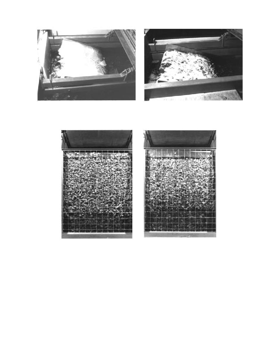
a. Ice riding up during a test run.
b. Riprap with shaved ice packed in the interstitial spaces
between the rocks after the ice sheet was removed at the
completion of a test.
Figure 16. Ride-up event.
a. Before.
b. After.
Figure 17. Model riprap before and after a test in which ice rode up the bank.
mm (2.1 in.). As shown in Figure 20a, the ice sheet
pieces (Fig. 20d). At this stage, no ice was being
broke into roughly rectangular-shaped pieces ap-
pushed off at the top edge of the bank because all
proximately 25 cm (10 in.) square as soon as the
the ice pieces piled up high, creating a steep in-
ice sheet contacted the bank above the waterline.
cline for the incoming ice sheet. Figure 20e and f
Figure 20b shows the broken-up ice sheet going
show that the ice sheet piled up and crushed into
the ice pile. In these last two views, it is possible
over the top edge of the bank and starting to pile
to see rocks being brought to the surface of the ice
up on one side of the riprap bank. Figure 20c shows
pile by the ice sheet. We observed the rocks being
the ice sheet riding up and over the top edge of
transported from the bed to the surface of the ice
the bank on one side of the model, and beginning
to pile up on the other side. As more of the ice
pile during most of the tests in which the ice piled
sheet continued to shove onto the bank, the ice
up on the bank.
At times, the ice sheet would buckle one or more
pieces stacked up on the previously deposited ice
13


 Previous Page
