EM 1110-2-2907
1 October 2003
surface types, a note of caution is required: make sure that differences within a type do
not drown out the differences between types.
(d) While spectral libraries have known targets that are "pure types," a pixel in a
remote sensing image very often includes a mixture of pure types: along edges of types
(e.g., water and land along a shoreline), or interspersed within a type (e.g., shadows in a
tree canopy, or soil background behind an agricultural crop).
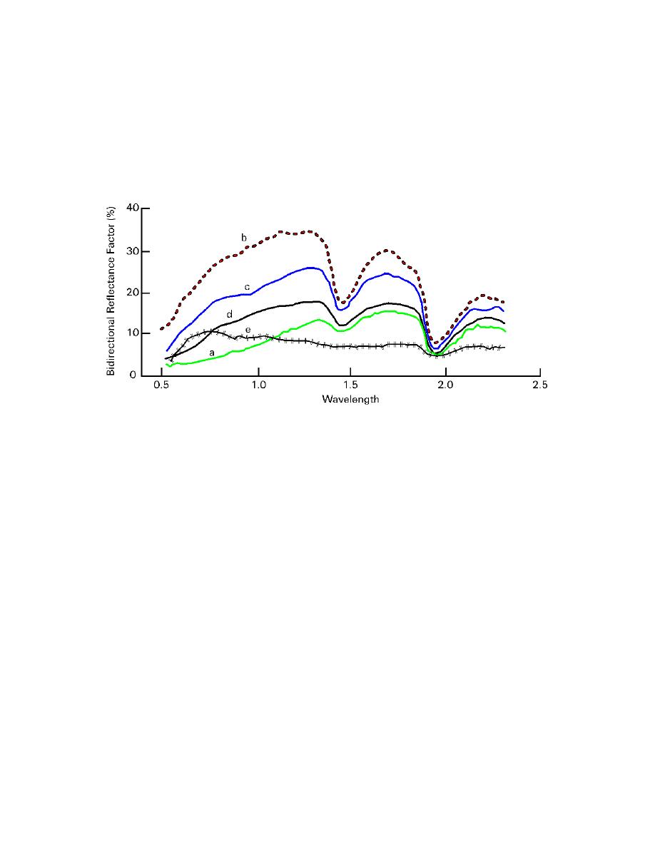
Figure 2-25. Reflectance spectra of five soil types: A--soils having > 2% organic matter
content (OMC) and fine texture; B-- soils having < 2% OMC and low iron content; C--soils
having < 2% OMC and medium iron content; D--soils having > 2% OMC, and coarse tex-
ture; and E-- soil having fine texture and high iron-oxide content (> 4%).
2-7 Component 4: Energy is Detected and Recorded by the Sensor. Earlier
paragraphs of this chapter explored the nature of emitted and reflected energy and the in-
teractions that influence the resultant radiation as it traverses from source to target to sen-
sor. This paragraph will examine the steps necessary to transfer radiation data from the
satellite to the ground and the subsequent conversion of the data to a useable form for
display on a computer.
a. Conversion of the Radiation to Data. Data collected at a sensor are converted from
a continuous analog to a digital number. This is a necessary conversion, as electromag-
netic waves arrive at the sensor as a continuous stream of radiation. The incoming radia-
tion is sampled at regular time intervals and assigned a value (Figure 2-26). The value
given to the data is based on the use of a 6-, 7-, 8-, 9-, or 10-bit binary computer coding
scale; powers of 2 play an important role in this system. Using this coding allows a com-
puter to store and display the data. The computer translates the sequence of binary num-
bers, given as ones and zeros, into a set of instructions with only two possible outcomes
(1 or 0, meaning "on" or "off"). The binary scale that is chosen (i.e., 8 bit data) will de-
mined by measuring the voltage of the incoming energy. Below in Table 2-5 is a list of
select bit integer binary scales and their corresponding number of brightness levels. The
ranges are derived by exponentially raising the base of 2 by the number of bits.
2-29


 Previous Page
